Lower body support device

a support device and lower body technology, applied in the direction of office stools, stilts, gymnastics, etc., can solve the problem of limiting the possibility of side-to-side motion, and achieve the effect of improving stability, facilitating replacement, and facilitating movemen

Inactive Publication Date: 2007-12-04
PETERSEN SCOTT J
View PDF16 Cites 5 Cited by
  • Summary
  • Abstract
  • Description
  • Claims
  • Application Information

AI Technical Summary

Problems solved by technology

The ankle frame and knee frame greatly limit the possibility of side-to-side motion.

Method used


Image

  • Lower body support device
  • Lower body support device
  • Lower body support device

Examples


Embodiment Construction

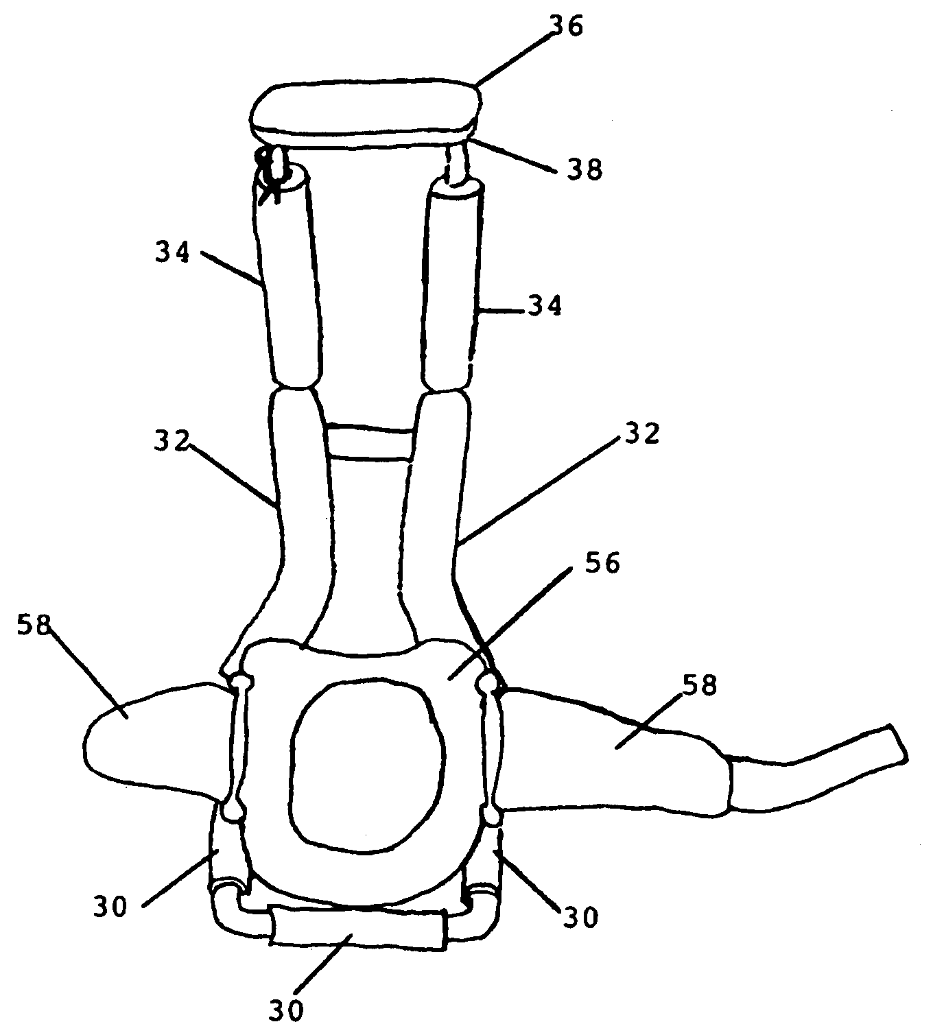
[0063]In its most simple configuration the lower body support device comprises three basic elements. First, there is a framing means 24 to support the leg of the user. Second there is a seating means 26 providing a region on which the user may sit. Once seated, a substantial amount of the user's body weight is transferred through the device, away from the user's leg, and onto the surface upon which the device rests. Third, there is a fastening means 28 for attaching the user to the device.

[0064]In the preferred embodiment of the invention, the framing means 24 is divided into three parts. As shown in FIG. 1, these parts are the knee frame 10, the bend frame 12, and the ankle frame 14.

[0065]Knee frame 10 receives the knee of the user. Knee frame 10 is designed to accommodate both the knee of the user as well as a knee pad 56 worn by the user. The user may choose a knee pad 56 to it within the region defined by knee frame 10. Such knee pad 56 should have knee pad straps 58 and may be ...


PUM


Abstract

A lower body support device is shown herein. The lower leg of the user is positioned such that the knee of the user rests within the area defined by a knee frame, the shin of the user rests within the area defined by a bend frame, and the ankle of the use rests in the region of an ankle frame. A strap bar means connected to the knee frame allows for the securing of a knee pad, such knee pad is user chosen, worn by the user and strapped to the knee frame via the strap bar means. A seat insert is secured to the top of the ankle frame. The user wears one leg support device on each leg. While resting on a surface, the bottom of the knee frame and the bottom of the ankle frame, and possibly the knee pad worn by the user, contact said surface. Preferably, the buttocks of the user rests on the seat insert, which transfers a significant portion of the weight of the user to the surface via the frames. The ankle frame and knee frame greatly limit the possibility of side-to-side motion. Additionally, the user may stand and walk while employing the leg support device.

Description

CROSS-REFERENCE TO RELATED APPLICATIONS[0001]Not applicableSTATEMENT REGARDING FEDERALLY SPONSORED RESEARCH OR DEVELOPMENT[0002]Not applicable.BACKGROUND[0003]1. Field of the Invention[0004]This invention is directed toward the field of lower body support devices. More particularly, this invention relates to a lower body support device for providing improved support, stability, and mobility for users of the device.[0005]2. Discussion of Prior Art[0006]Many occupations require workers to assume kneeling positions in order to attend the task for which they are employed. Unfortunately, assuming a kneeling position for an extended period, or repeatedly, causes those in such a position discomfort, cramping, muscle fatigue, or other similar problems.[0007]Many devices have been proposed over the years to alleviate the discomforts associated with kneeling positions. For instance, U.S. Pat. No. 1,296,522 to Holsey shows a simple knee pad device. Similarly, U.S. Pat. No. 1,547,166 to Davidis...

Claims


Application Information

Patent Timeline
Patent Type & Authority Patents(United States)
IPC IPC(8): A63B26/00
CPCA47C9/005A47C9/025Y10S482/907
Inventor PETERSEN, SCOTT J.
Owner PETERSEN SCOTT J
Why Eureka
Try Eureka