
Compound conversion plug structure with adjustable angle and adapter

a plug structure and angle adjustment technology, applied in the direction of flexible lead accommodation, two-part coupling devices, coupling device connections, etc., can solve the problems of inconvenience for users, adapter cannot be used with a corresponding socket, adapter cannot be used, etc., to reduce manufacturing costs

Inactive Publication Date: 2007-12-04
LIAO SHENG HSIN
View PDF15 Cites 30 Cited by
  • Summary
  • Abstract
  • Description
  • Claims
  • Application Information

AI Technical Summary

Benefits of technology

[0007]An object of the present invention is to provide a compound conversion plug structure with an adjustable angle and adapter, which can be inserted into two similar types and standards of sockets to satisfy consumer demands, and reduce manufacturing costs.
[0011]1. When the plug component isn't in use, via the protruding poles and the sliding grooves, the plug component can slide between the two side arms and rotate in different directions; hence, it is unnecessary to disassemble the plug component when only the plug component needs to be used, so it is more convenient for users.2. Because of the structure of the moving block and the transfer piece of the adapter, the metal inserting pieces can be inserted into two types and standards of sockets to satisfy consumer demands and reduce manufacturing costs.

Problems solved by technology

However, the adapter can only be used with a corresponding socket.
If there is another type of socket then the adapter cannot be used.
This causes inconvenience for users because they need to buy another type of adapter.
For manufacturers costs are increased by necessitating the manufacture of more types of adapters.

Method used


Image

  • Compound conversion plug structure with adjustable angle and adapter
  • Compound conversion plug structure with adjustable angle and adapter
  • Compound conversion plug structure with adjustable angle and adapter

Examples


Embodiment Construction

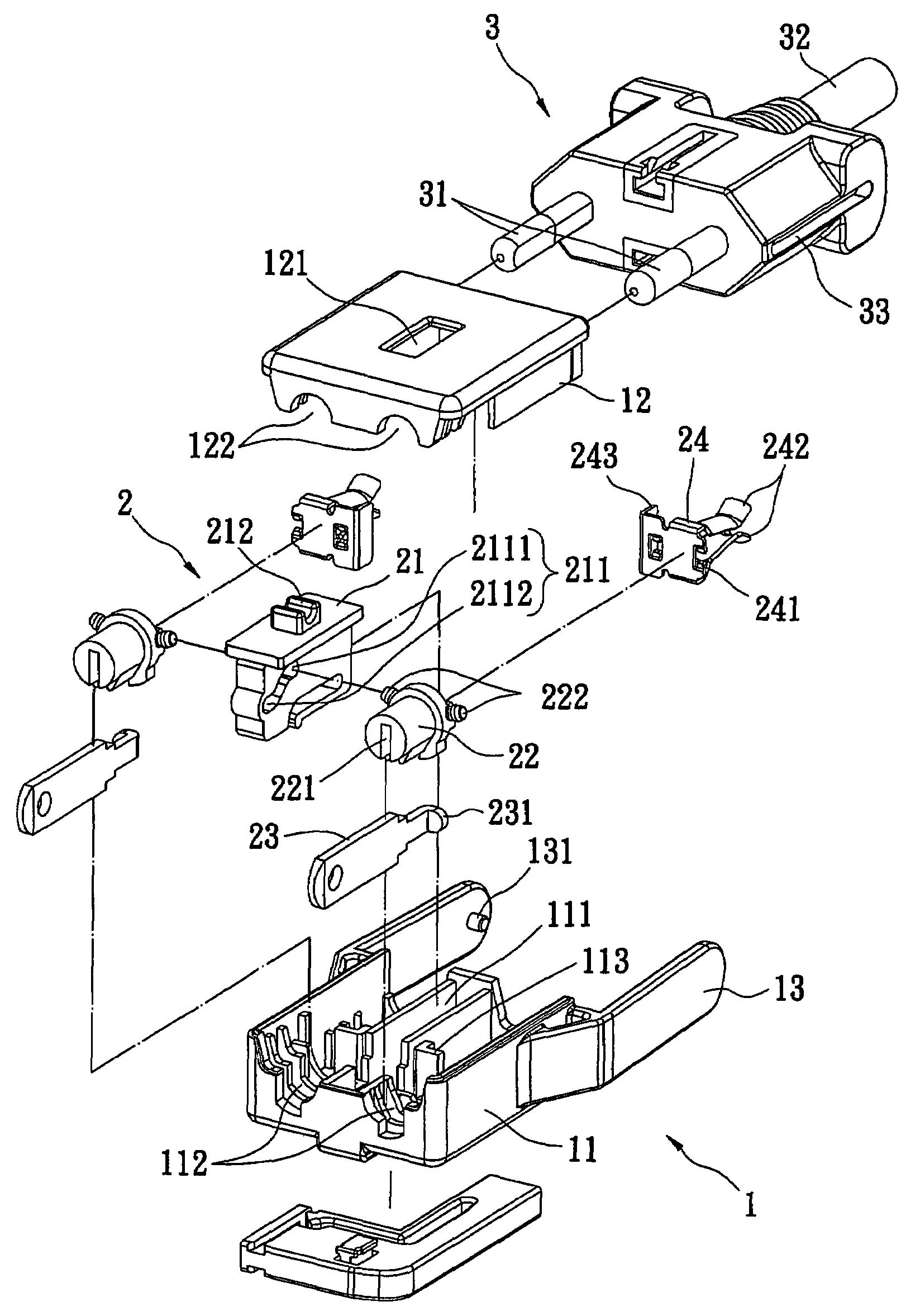
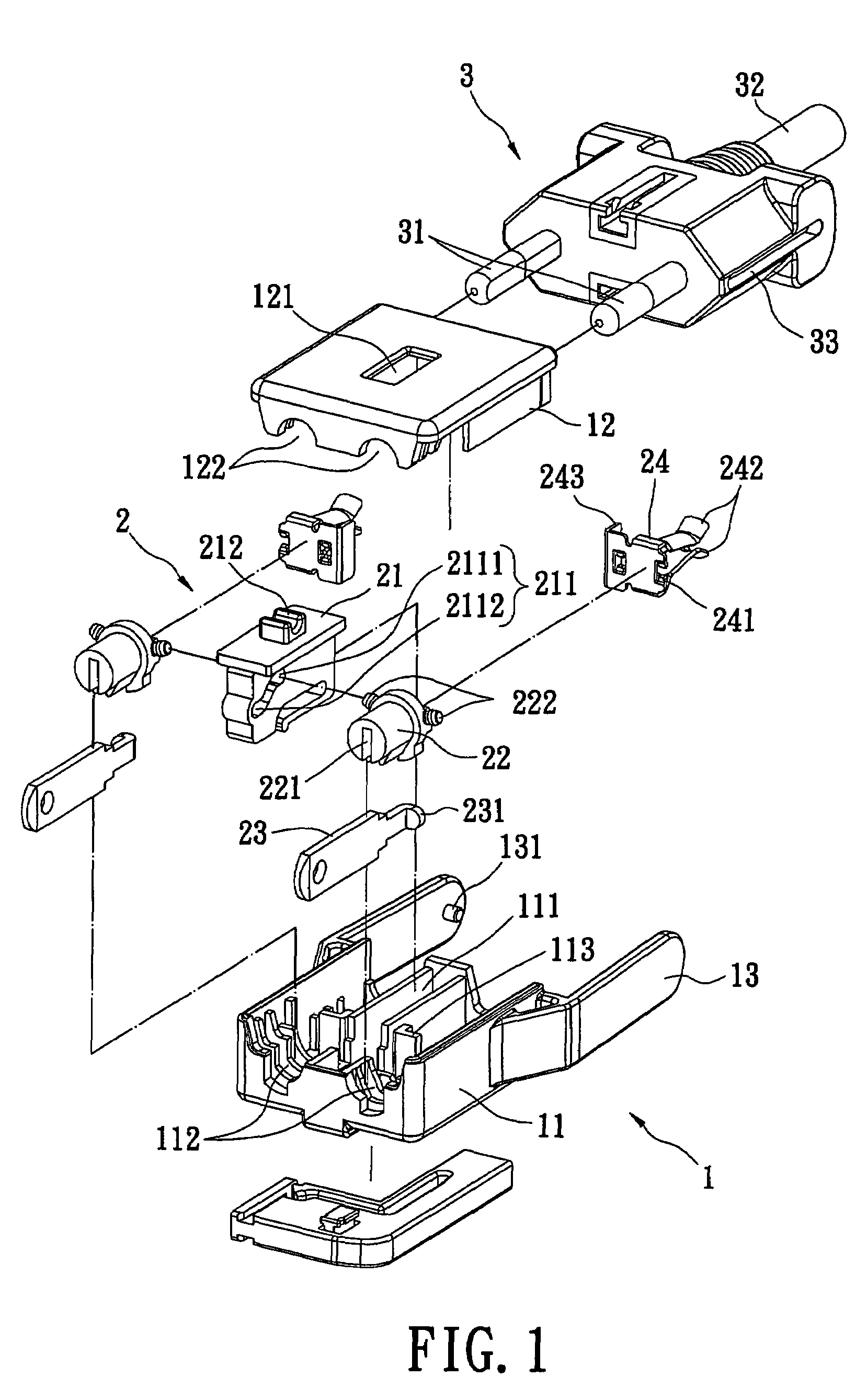
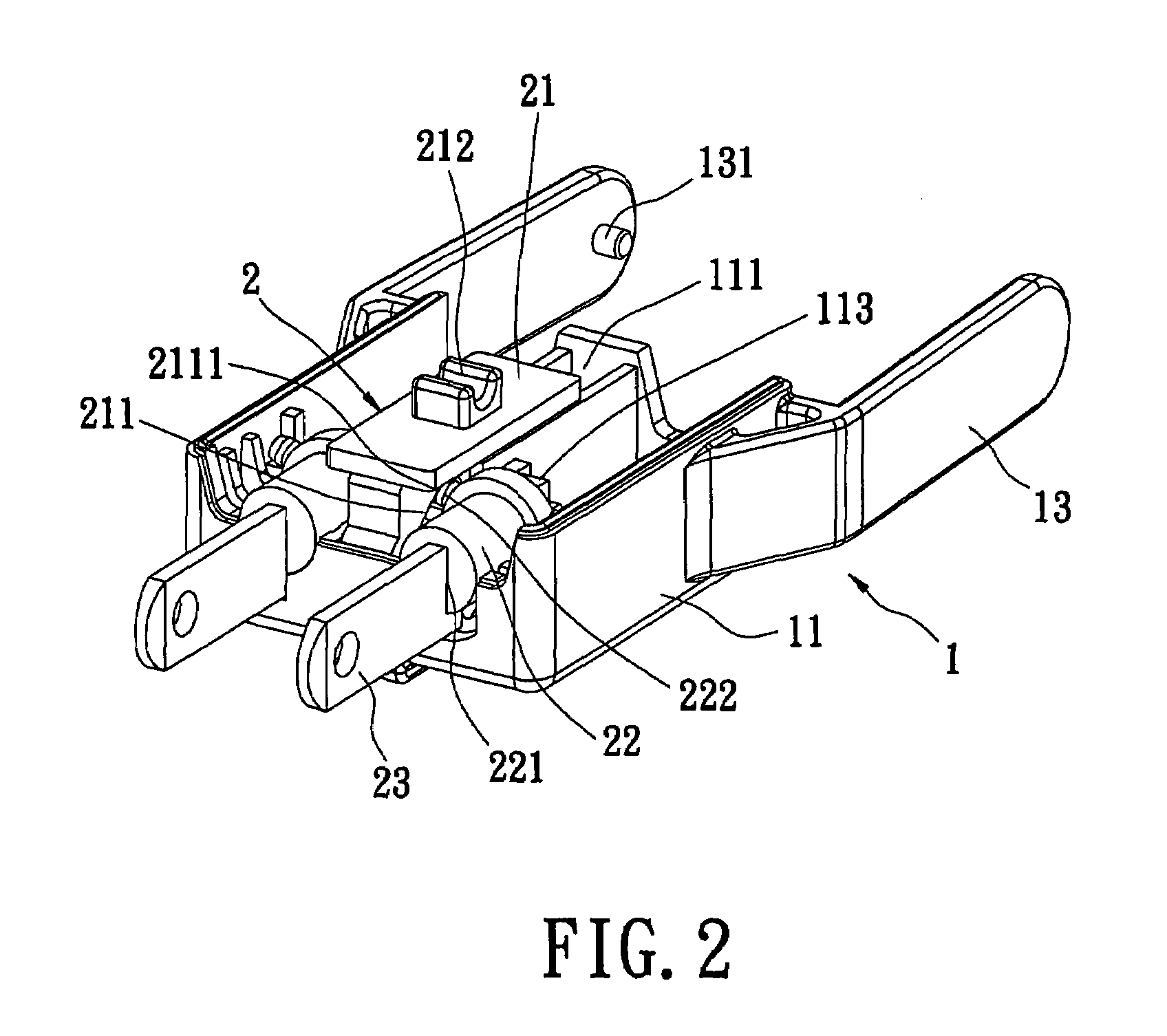
[0023]Referring to FIGS. 1-2, a compound conversion plug structure with an adjustable angle of the present invention is shown. The compound conversion plug structure includes an outer shell 1, a moving machine 2, and a plug component 3. The outer shell 1 and the moving machine 2 together form an adapter.

[0024]The outer shell 1 includes an integrating base 11, an integrating cover 12, and two side arms 13. A groove 111 is defined at the center of the integrating base 11. Two first containing portions 112 are defined concavely and two L-shaped locating blocks 113 protrude near two outsides of the groove 111 respectively. A notch 121 is defined on the surface of the integrating cover 12. Two second containing portions 122 are defined concavely below an end of the integrating cover 12.

[0025]The two side arms 13 integrate with the two side edges of the integrating base 11 by an in-molding method respectively, or alternatively, by a pivoting method with the two side edges thereof respecti...


PUM


Abstract

A compound conversion plug structure with an adjustable angle includes an adapter and a plug component. The adapter includes an outer shell, a moving block, a plurality of transfer pieces, a plurality of metal inserting pieces, and a plurality of engaging pieces. The moving block defines a guiding groove thereon, and protruding pieces defined on the transfer pieces respectively are set in the guiding groove, the metal inserting pieces are assembled with the transfer pieces, one end of which extends out of the outer shell, and additional ends of the metal inserting pieces engage with the engaging pieces respectively. Because of the structure of the moving block and the transfer piece of the adapter, the metal inserting pieces can be inserted into two types and standards of sockets. Hence, the adapter provides multiple changes to suite actual needs.

Description

BACKGROUND OF THE INVENTION[0001]1. Field of the Invention[0002]The present invention relates to a compound conversion plug structure, and more specifically to an adapter capable of transfer engaging, and a plug component that can slide and be assembled with the adapter. The adapter suits two standards and types of sockets.[0003]2. Description of the Prior Art[0004]Usually a power supply cord and an electronic device are connected electronically by inserting a plug set on one end of the power supply cord into a corresponding socket. In this manner the power supply cord and the electronic device are connected electronically by the electronical connection between the power supply cord and the electronic device. However, if the standard and type of the plug is different from that of the socket, it is necessary to assemble the plug with an adapter, and then to insert the adapter plug into the socket to connect the plug with the socket electronically.[0005]However, the adapter can only b...

Claims


Application Information

Patent Timeline
IPC IPC(8): H01R29/00
CPCH01R13/633H01R13/6675H01R13/72H01R27/00H01R31/06H01R24/28H01R2103/00
Inventor LIAO, SHENG-HSIN
Owner LIAO SHENG HSIN
Learn More