
Adjustable fixing mount

Inactive Publication Date: 2007-12-04
SUPA TECH
View PDF9 Cites 70 Cited by
  • Summary
  • Abstract
  • Description
  • Claims
  • Application Information

AI Technical Summary

Benefits of technology

[0006]An adjustable fixing mount according to the present invention is provided to solve the drawback of the conventional fixing mount that cannot freely adjust the horizontal angle and the pitch angle to fit the ergonomic principle and human habit.
[0009]Another objective of the present invention is to provide an adjustable fixing mount with a sucking disc on the seat to be attached to and fixed on a surface of an object. Such design is convenient to attach to and remove from a plane surface everywhere, anytime.
[0010]A further objective of the present invention is to provide an adjustable fixing mount with simple structure and easy to use. Thus it could replace all kinds of conventional fixing mounts for economical efficiency.

Problems solved by technology

However, how to place these communication equipments becomes a problem when the users drive or ride a vehicle.
The conventional fixing mount is a rigid body so that the user cannot adjust the height, angle or direction.
Therefore, the fixing mount is inconvenient to operate because it is against the ergonomics and the user's habit.
It cannot work well as a tool for the communication equipment.

Method used


Image

  • Adjustable fixing mount
  • Adjustable fixing mount
  • Adjustable fixing mount

Examples


Embodiment Construction

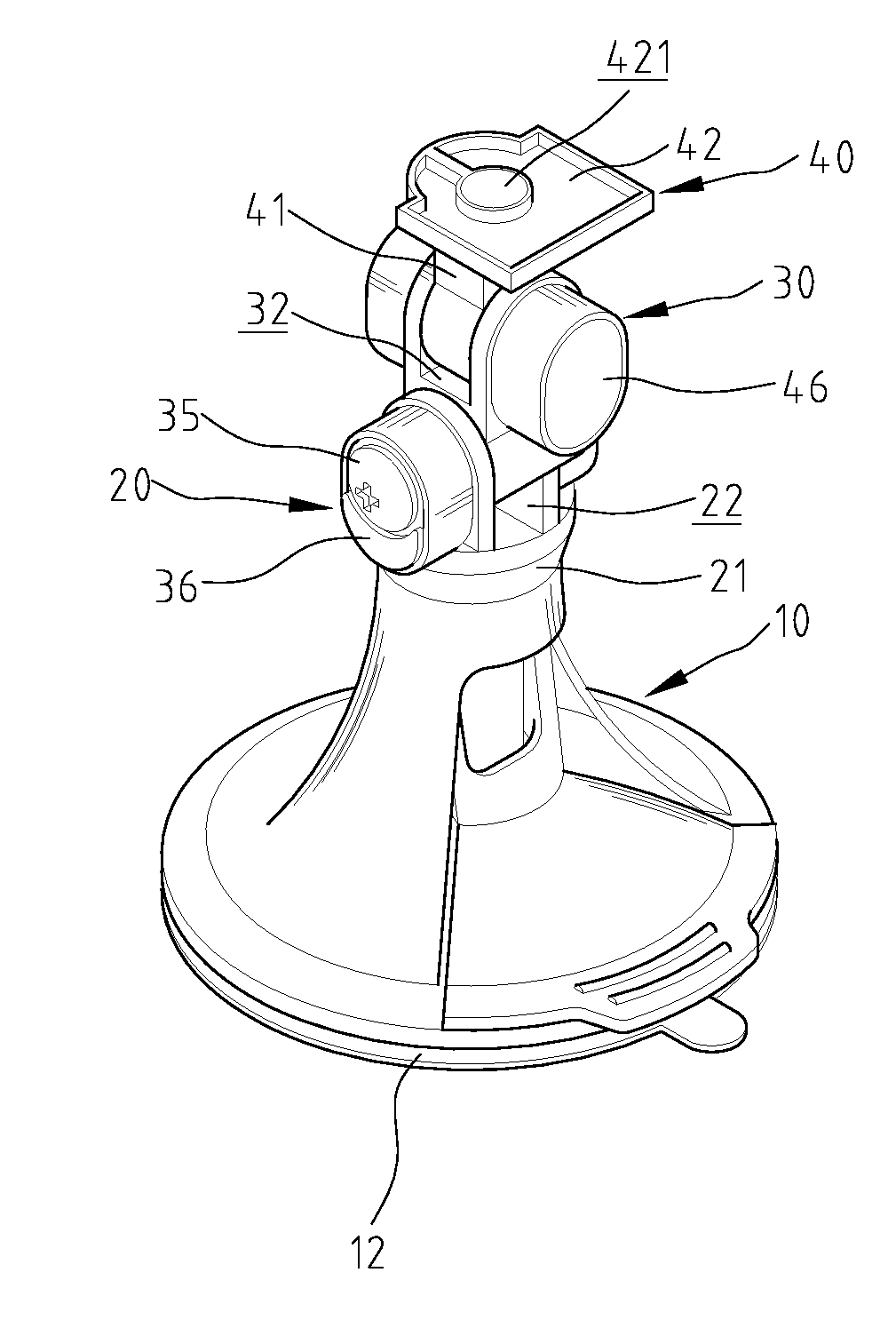
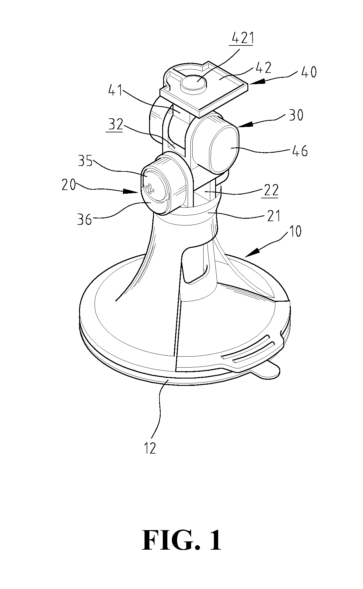
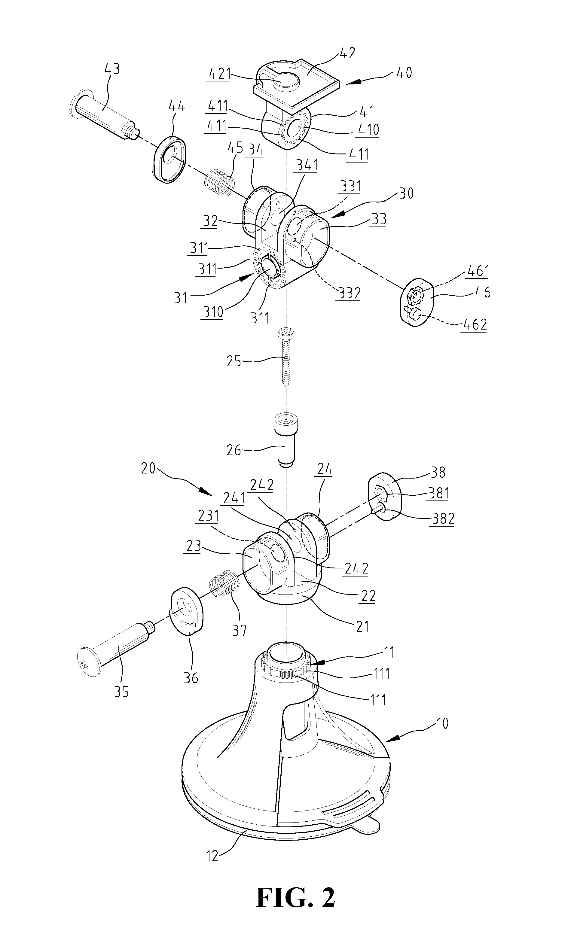
[0027]With reference to the FIGS. 1 and 2, the adjustable fixing mount constructed in accordance with the present invention comprises a seat 10, a horizontal rotary device 20, a pitch-adjusting device 30 and a swing-adjusting device 40.

[0028]The top of the seat 10 is provided with a horizontal annular gear section 11. The gear section 11 has a plurality of cogs at an outer rim. The bottom of the seat 10 is provided with a sucking disc 12 made of a tenacious material to attach to a plane surface of an object.

[0029]The horizontal rotary device 20 comprises a hollow annular integration seat 21 whose inner rim includes a plurality of elastic pieces 211. Referring to FIG. 7, both ends of the elastic piece 211 are fixed at the inner rim of the integration seat 21, and an arc hollow gap 210 is formed between the integration seat 21 and the elastic piece 211. The elastic piece 211 has at least one projection 212 at the side towards the axial direction of the adjustable fixing mount. The pro...


PUM


Abstract

An adjustable fixing mount for communication equipment comprises a seat, a horizontal rotary device, a pitch-adjusting device and a swing-adjusting device. The horizontal rotary device is mounted on the seat and is capable of rotating freely to adjust the horizontal angle. The pitch-adjusting device is disposed on the horizontal rotary device and is capable of rotating freely to adjust the pitch angle. The swing-adjusting device is disposed on the pitch-adjusting device and is capable of rotating freely to adjust the swing angle. The upper part of the swing-adjusting device includes an equipment seat to hold the communication equipment. The adjustable fixing mount could adjust the communication equipment toward an appropriate direction and angle.

Description

BACKGROUND OF THE INVENTION[0001]1. Field of the Invention[0002]The present invention relates generally to a fixing mount, and in particular to an adjustable fixing mount for the communication equipments that is capable of sucking on a plane surface and adjust the horizontal angle and pitch angle. Thus, the communication equipment is directed toward the most appropriate direction and angle.[0003]2. The Prior Arts[0004]Nowadays all kinds of communication equipments such as mobile phones, PDA's, GPS's, etc provide convenient communication. Users may get in touch with others anywhere and anytime. However, how to place these communication equipments becomes a problem when the users drive or ride a vehicle.[0005]Although conventional fixing mounts for communication equipments provide to hold all kinds of communication equipments in a vehicle, it has some shortcomings in common. The conventional fixing mount is a rigid body so that the user cannot adjust the height, angle or direction. Th...

Claims


Application Information

Patent Timeline
IPC IPC(8): F16M11/14
CPCB60R11/00B60R11/02F16M11/105F16M11/14F16M11/2064F16M13/022F16M11/12B60R2011/0005B60R2011/0056B60R2011/0089Y10S224/908F16M2200/041F16M2200/044
Inventor CHEN, JEONG-SHIUN
Owner SUPA TECH
Learn More