Eureka AIR delivers breakthrough ideas for toughest innovation challenges, trusted by R&D personnel around the world.

Composite camera system, zoom camera image display control method, zoom camera control method, control program, and computer readable recording medium

a camera system and camera control technology, applied in the field of composite camera systems, can solve the problems of insufficient monitoring of large instruments, inability to obtain accurate information, and inability to accurately monitor large instruments, etc., and achieve the effect of convenient control

Active Publication Date: 2007-11-27
TOA CORP
View PDF15 Cites 20 Cited by
  • Summary
  • Abstract
  • Description
  • Claims
  • Application Information

AI Technical Summary

Benefits of technology

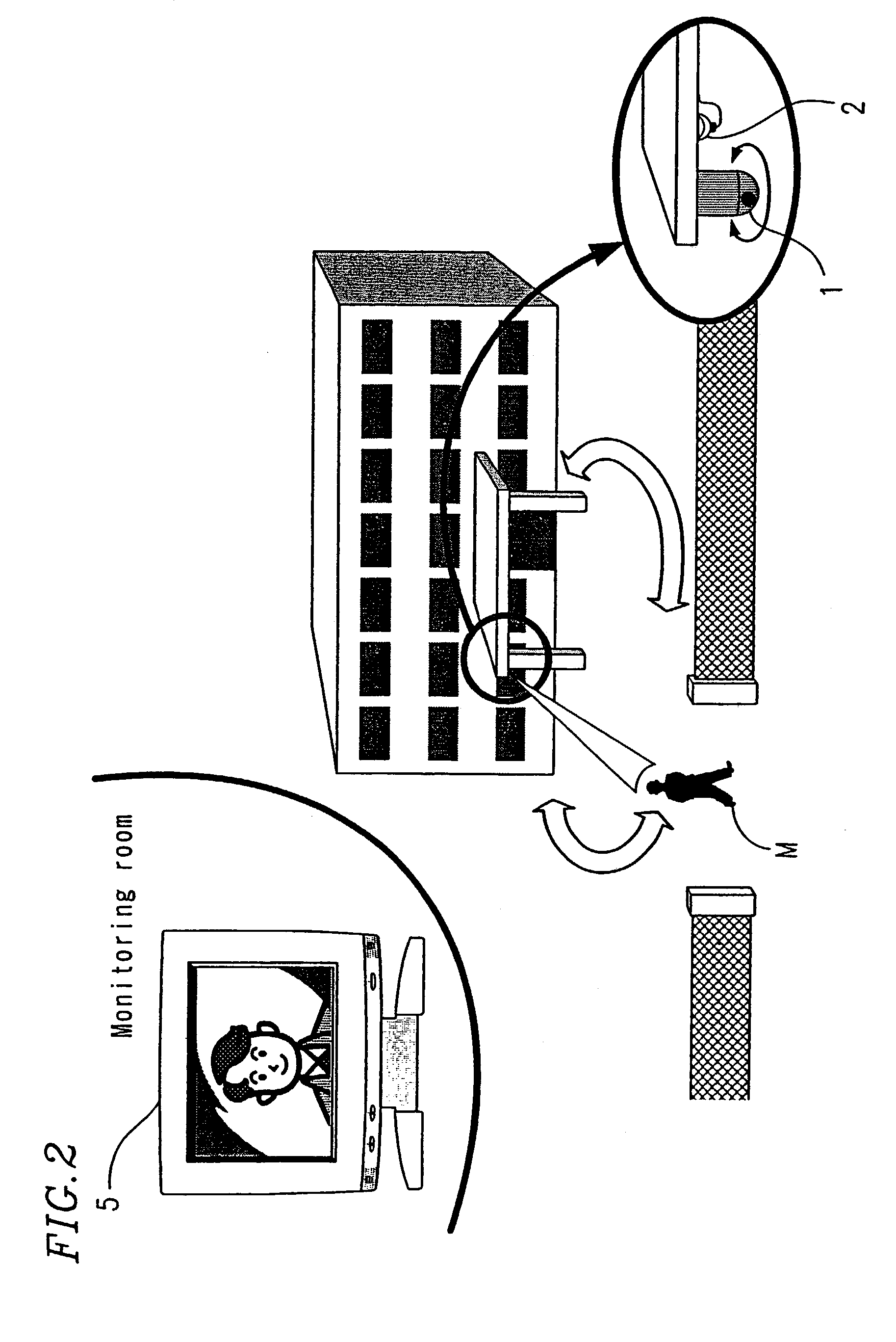
[0034]As described above, according to the present invention, positional control and magnification ratio control of the zoom camera are performed centered on a prescribed portion of omnidirectional image data, and the omnidirectional image and the zoom image are displayed. The omnidirectional camera is used to photograph a plurality of important locations simultaneously as included in the omnidirectional image, and the zoom camera is used to zoom-photograph a specified image area in the omnidirectional image. By specifying a prescribed image area in the omnidirectional image, the position of the zoom camera can be easily set.
[0038]In the case where a circular omnidirectional image is divided into a plurality of image areas, and control information is set for controlling the zoom camera to be at a prescribed position and to have a prescribed magnification ratio for each of the plurality of image areas, the division can be performed effectively and the image areas can be displayed so as to be easily identifiable.
[0040]An image area, in the omnidirectional image, which is unstable due to environmental influence can be invalidated in advance. Therefore, a moving body or an abnormality can be accurately detected automatically from the omnidirectional image, so that the position and the magnification ratio of the zoom camera is accurately controlled for the detected moving body or the site of the abnormality.
[0043]Thus, the invention described herein makes possible the advantages of providing a composite camera system for photographing a plurality of important locations simultaneously as included in an omnidirectional image using an omnidirectional camera, and zoom-photographing a specified image area in the omnidirectional image with the position of a zoom camera being easily controlled; a zoom camera image display control method and a zoom camera control method using the same; a control program usable for the same; and a computer readable recording medium having the program stored therein.

Problems solved by technology

A monitoring instrument for allowing the manager to monitor a video taken by the monitoring camera on a screen of a monitoring device is inevitably large-sized and can be quite expensive.
Even such a large instrument is still insufficient for accurately monitoring a target of crime prevention at a remote location.
When such a security device using such a sensor gives an alarm, the manager can recognize that an abnormality has occurred, but cannot obtain accurate information by visually checking the degree or details of the abnormality.
In addition, certain types of sensor can only detect an abnormality of the respective type.
There are other problems in that the reliability of the sensors dispersed may be lowered, and it is difficult to control the position of the TV camera with respect to the sensors.
Therefore, abnormalities only at sites where the sensors are located can be detected.
There are other problems in that the sensors may malfunction because of the environment in which the sensors are located, and it is troublesome to control the position of the TV camera with respect to the various sensors.

Method used


Image

  • Composite camera system, zoom camera image display control method, zoom camera control method, control program, and computer readable recording medium
  • Composite camera system, zoom camera image display control method, zoom camera control method, control program, and computer readable recording medium
  • Composite camera system, zoom camera image display control method, zoom camera control method, control program, and computer readable recording medium

Examples


Embodiment Construction

[0055]Hereinafter, the present invention will be described by way of illustrative, but non-limiting examples with reference to the accompanying drawings.

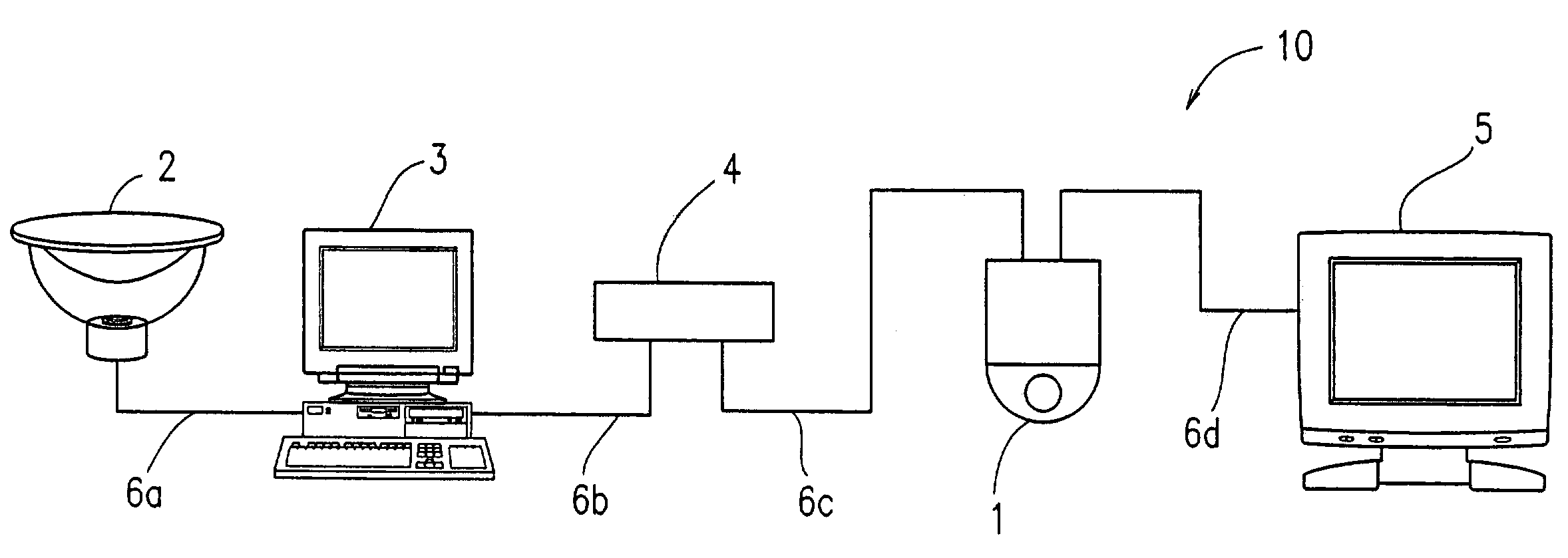
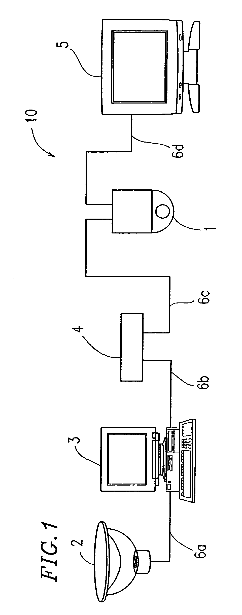
[0056]FIG. 1 is a schematic view illustrating a basic structure of a composite camera system 10 according to an example of the present invention.

[0057]In FIG. 1, the composite camera system 10 includes a zoom camera 1, an omnidirectional camera 2, a remote controller 3, a zoom camera control unit 4 acting as a zoom camera control section, a monitor 5, and communication lines 6a through 6d for connecting these elements so that these elements can communicate with each other.

[0058]The zoom camera 1 includes, for example, a zoom lens, an imaging section (photographing section) including CCDs, and a driving section for driving and controlling the zoom lens to pan (to move to a prescribed position in a horizontal direction), to tilt (to move to a prescribed position in a vertical direction) and to zoom (to have a prescribed magnification ...


PUM


Abstract

A composite camera system includes a control section for performing positional control and magnification ratio control of at least one zoom camera ratio for omnidirectional image data centered on a prescribed portion thereof, the omnidirectional image data being obtained by an omnidirectional camera capable of taking an omnidirectional image over a viewing angle of a maximum of 360 degrees; and a display section for displaying an omnidirectional image taken by the omnidirectional camera and a zoom image taken by the zoom camera.

Description

BACKGROUND OF THE INVENTION[0001]1. Field of the Invention[0002]The present invention relates to a composite camera system for taking an omnidirectional image using an omnidirectional camera capable of capturing information of a viewing angle of a maximum of 360 degrees, and zoom-photographing an area including an image area which is automatically or manually specified from the omnidirectional image by a zoom camera; a zoom camera image display control method and a zoom camera control method using the same, a control program usable for the same, and a computer readable recording medium having the program stored therein.[0003]2. Description of the Related Art[0004]Monitoring cameras conventionally and generally known as used in security devices installed in, for example, financial institutions and supermarkets include fixed-type and pivotable cameras. Usually, a manager checks a video taken by such a monitoring camera using a monitoring device or the like in the manager's office, so ...

Claims


Application Information

Patent Timeline
IPC IPC(8): H04N7/18H04N5/225G03B37/00G08B13/194G08B13/196G08B15/00G08B25/04H04N5/232
CPCG08B13/19602G08B13/19628G08B13/19643G08B13/19652G08B13/19656H04N7/188G08B13/19689G08B13/19691H04N5/23238H04N7/181G08B13/1968H04N23/698
Inventor KAKOU, NORITOSHIFUKUHARA, YOSHIOMISAWA, MASAHIRO
Owner TOA CORP
Why Eureka
Eureka Blog
Learn More