Heat resistant lithium cell
a lithium cell and heat resistance technology, applied in the field of lithium cell electrolyte improvement, can solve the problems of insufficient heat resistance, cell cannot be used in the above fields of application, and cells are often exposed to harsh temperature environments of over 100 to 150° c, so as to improve discharge characteristics and increase internal resistance
Active Publication Date: 2007-11-27
FDK CORP
View PDF11 Cites 3 Cited by
- Summary
- Abstract
- Description
- Claims
- Application Information
AI Technical Summary
Benefits of technology
[0031]When carboxylic acid, carboxylic acid ester, or carboxylic acid anhydride (there are cases where they are referred to as carboxylic acids and the like) is added as an additive in the nonaqueous electrolyte, this additive reacts with the negative electrode and forms a highly conductive
Problems solved by technology
Conventional lithium cells can be used in a temperature environment of up to approximately 85° C. However, when lithium cells are incorporated into electrical components of vehicles (air-pressure gauges for tires, on-vehicle devices of the Electronic Toll Collection system, and the like), FA (Factory Automation) appliances, and the like, the cells are often exposed to a harsh temperature environment of over 100 to 150° C.
However, with the technique disclosed in H1-281677, heat resistivity is insufficient because the separator and gasket used here are made of low heat-resistant polypropylene (melting point: approximately 150° C.).
For this reason, the cells cannot be used in the above fields of application, where a long period of stability against temperatures of near 150° C. is required, and also cannot be used in reflow soldering, where a cell is exposed to temperatures of at least 200° C.
This lowers the ionic conductivity of
Method used
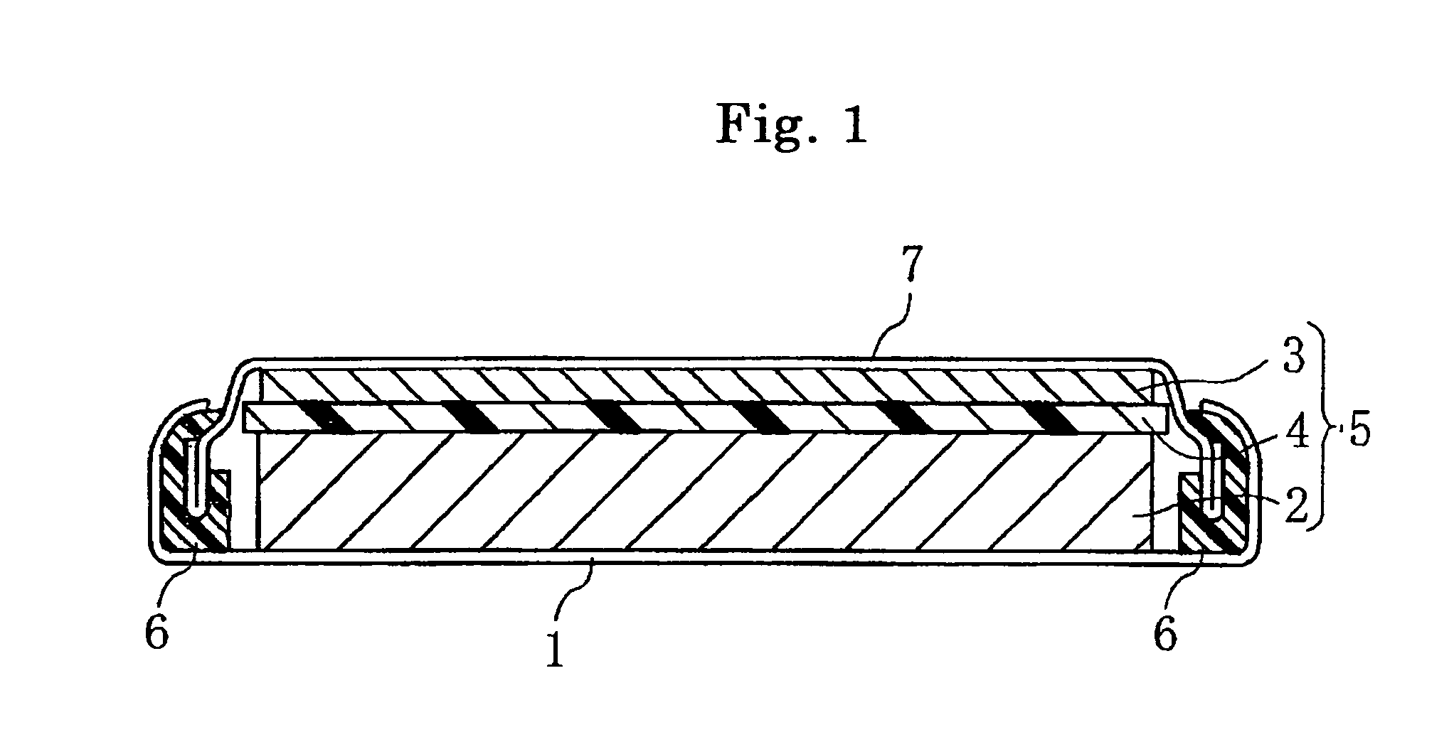
View moreImage
Smart ImageViewing Examples
Examples
 PUM
 Abstract
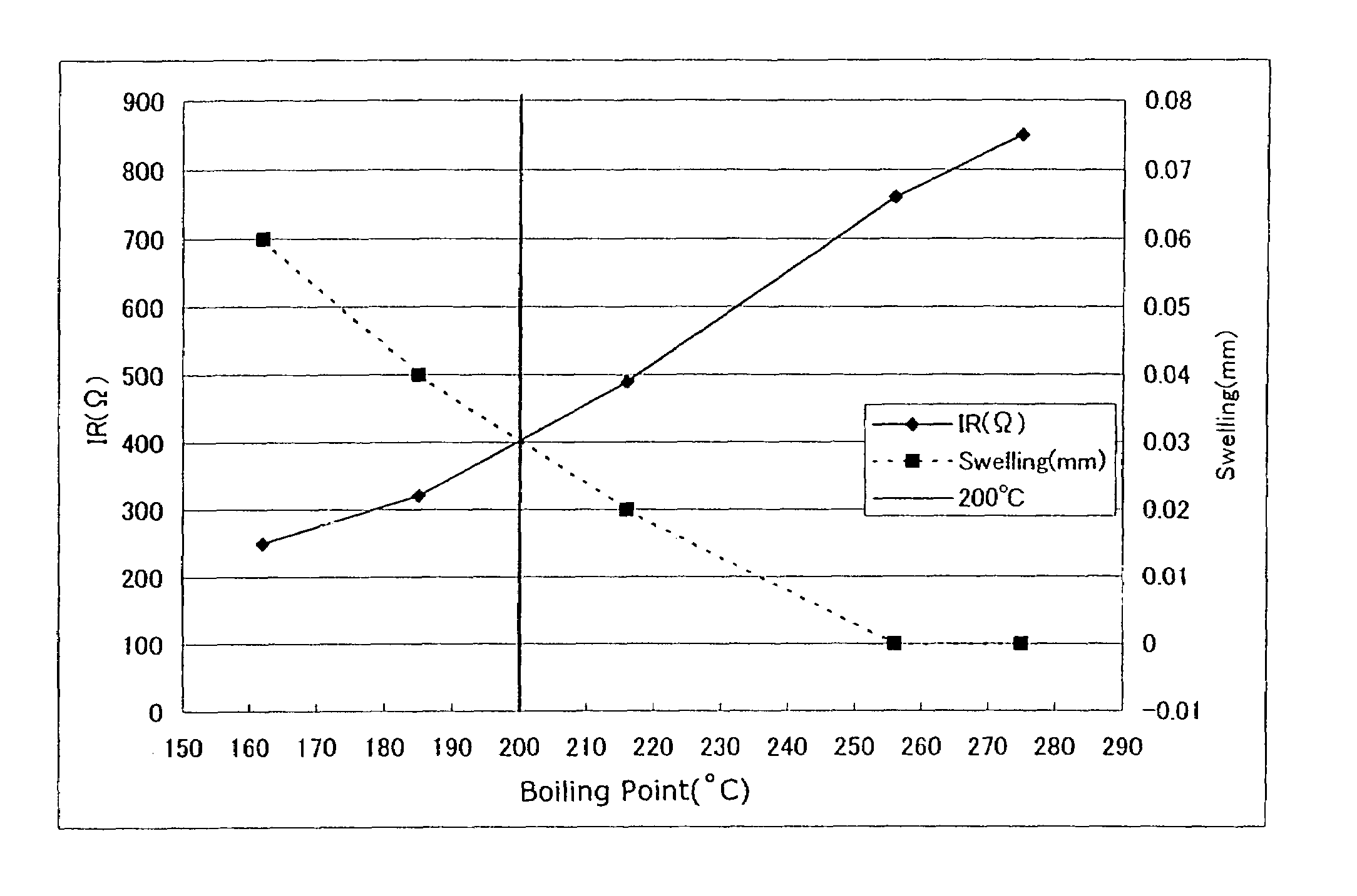
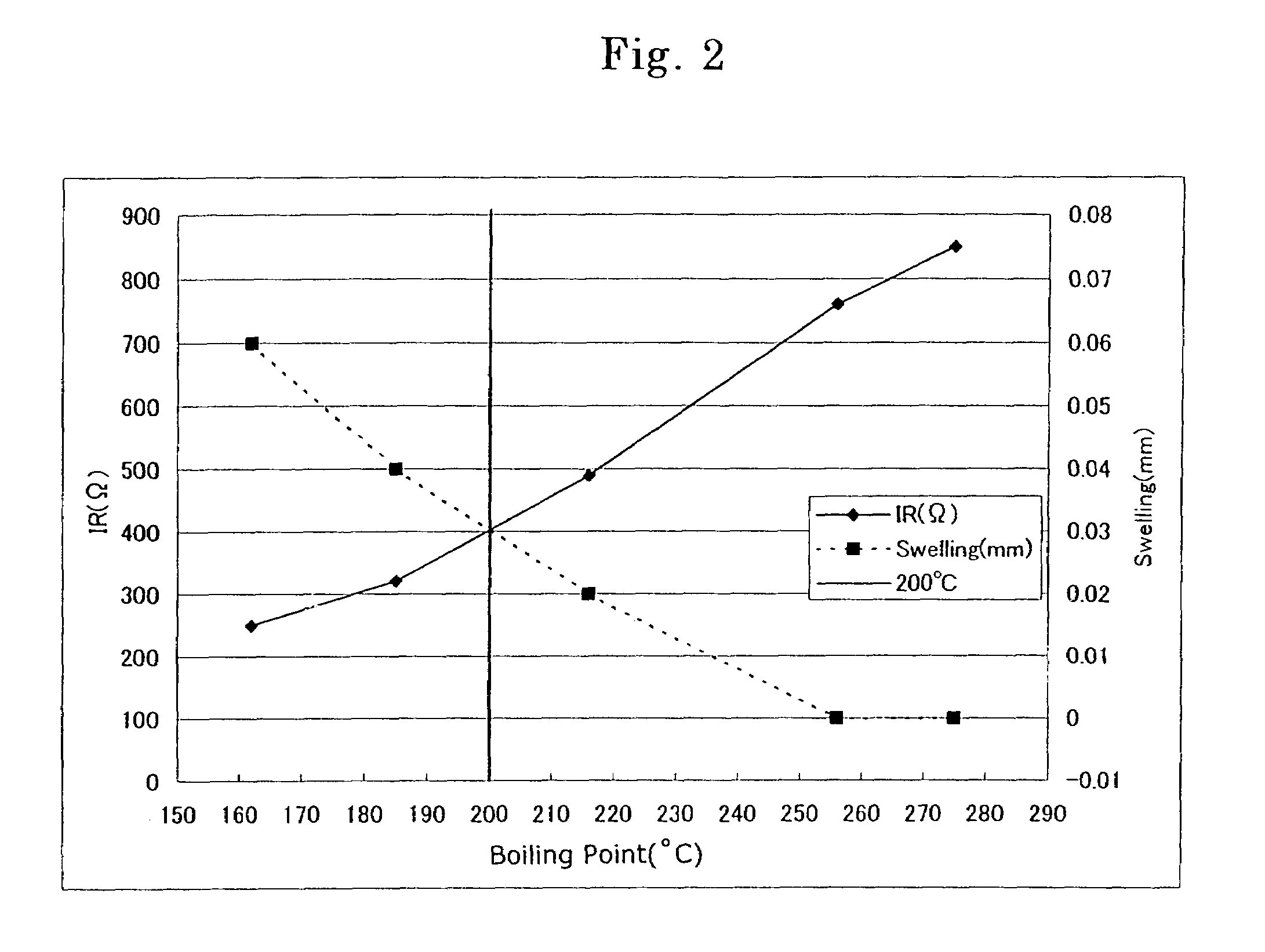
The present invention provides a cell that does not impair heat resistant safety and electrochemical characteristics such as a discharge characteristic, and enhances long-period reliability. In the cell of the present invention, a nonaqueous solvent has, among compounds represented by the following general formula (1), at least one solvent having a boiling point of 200° C. or higher, and has, among compounds represented by the following general formula (1), at least one solvent having a boiling point of lower than 200° C.; and the total volume ratio at 23° C. of the compounds represented by the following general formula (1) is 95 to 100 percent of the nonaqueous solvent,
X—(O—C2H4)n-O—Y (1)
(where X and Y are independently an alkyl group (number of carbons: 1-4), and n is 1-5).
Description
BACKGROUND OF THE INVENTION[0001](1) Field of the Invention[0002]The present invention relates to an improvement of an electrolyte of lithium cells.[0003](2) Description of the Prior Art[0004]Conventional lithium cells can be used in a temperature environment of up to approximately 85° C. However, when lithium cells are incorporated into electrical components of vehicles (air-pressure gauges for tires, on-vehicle devices of the Electronic Toll Collection system, and the like), FA (Factory Automation) appliances, and the like, the cells are often exposed to a harsh temperature environment of over 100 to 150° C.[0005]To enhance productivity, when the cells are incorporated into electronic appliances, the technique of reflow soldering is employed. With this technique, a cell temperature reaches, though only temporarily, as high as 200 to 260° C. In view of this, there is a need for highly reliable lithium cells in heat resistivity that do not swell or do not deteriorate their cell char...
Claims
Login to View More Application Information
Patent Timeline
 IPC IPC(8): H01M6/16H01M6/14H01M10/052H01M10/0567H01M10/0568H01M10/0569H01M10/36
CPCH01M10/052H01M10/0567H01M10/0569H01M10/0568Y02T10/7011H01M2300/0025H01M2300/004Y02E60/122Y02E60/10F24F6/16Y02T10/70
Inventor FUKUOKA, SATORUMORITA, SEIJINISHIGUCHI, NOBUHIRONARUSE, SATORUMURAKI, MASAYUKIIMANISHI, MASAHIRO
Owner FDK CORP
Features
- R&D
- Intellectual Property
- Life Sciences
- Materials
- Tech Scout
- Unparalleled Data Quality
- Higher Quality Content
- 60% Fewer Hallucinations
Learn More Browse by: Latest US Patents, China's latest patents, Technical Efficacy Thesaurus, Application Domain, Technology Topic, Popular Technical Reports.
© 2025 PatSnap. All rights reserved.Legal|Privacy policy|Modern Slavery Act Transparency Statement|Sitemap|About US| Contact US: help@patsnap.com


