
Method and system for inspecting objects using ultrasound scan data

a technology of ultrasound scan data and inspection method, applied in the field of inspection system, can solve problems such as pipeline integrity degradation, corrosion or other pipeline defects, potential defects and anomalies on the surface of pipelines

Active Publication Date: 2007-11-27
GENERAL ELECTRIC CO
View PDF21 Cites 57 Cited by
  • Summary
  • Abstract
  • Description
  • Claims
  • Application Information

AI Technical Summary

Benefits of technology

The solution provides more accurate and automated crack depth estimation, reducing manual analysis time and subjectivity, thereby enhancing the efficiency and reliability of pipeline maintenance and repair processes.

Problems solved by technology

Underground and underwater (deep sea) pipelines typically carry enormous quantities of oil and gas products that are important to energy-related industries, often under extreme conditions such as high pressure, high (or low) temperature and high flow rate.
Flaws in constituent pipes may cause pipeline integrity degradation as the pipeline infrastructure ages.
Corrosion or other pipeline defects can be caused by small spots of weakness, subsidence of the soil, local construction projects, seismic activity, weather, wear and tear caused by normal use, and the like.
Accordingly, potential defects and anomalies can appear on the surface of the pipeline in the form of corrosion, mechanical damage, fatigue cracks, stress corrosion cracks, hydrogen-induced cracks, or distortion because of dents or wrinkles.
Maintaining and protecting existing pipeline networks is proving to be a challenge.
The process of analyzing data obtained from the PIG and making practical use of the analysis is often burdensome.
Without accurate information regarding flaw size, it may be difficult to rate the quality of the pipeline or perform any remaining life estimation studies for such objects.
Manual crack sizing leads to subjectivity and operator dependence, which in turn, might lead to inconsistent sizing estimates.
The use of amplitude data alone may not be reliable when trying to identify cracks or crack-like flaws, since the amplitude of the reflected sound signal depends on shape, size, type, orientation and position of the crack or crack-like flaw.

Method used


Image

  • Method and system for inspecting objects using ultrasound scan data
  • Method and system for inspecting objects using ultrasound scan data
  • Method and system for inspecting objects using ultrasound scan data

Examples


Embodiment Construction

[0016]The various aspects of the present technique deal with identifying and estimating the depth of cracks and crack-like flaws in objects. Though the aspects have been described in relation to pipeline applications, the techniques described herein are equally applicable in other environments, for example, estimating the depth of cracks and crack-like flaws in rail tracks or in plates or bars.

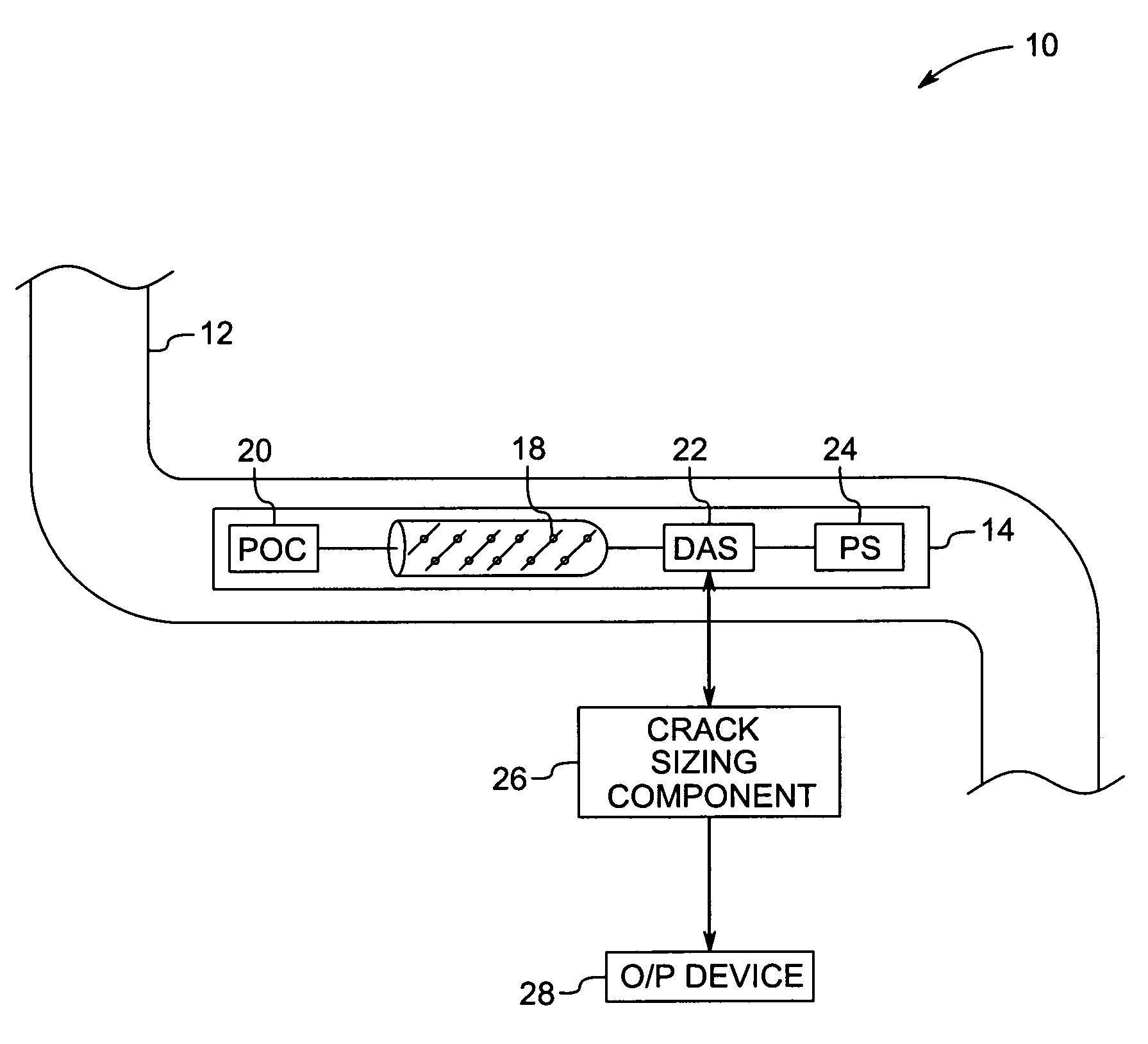
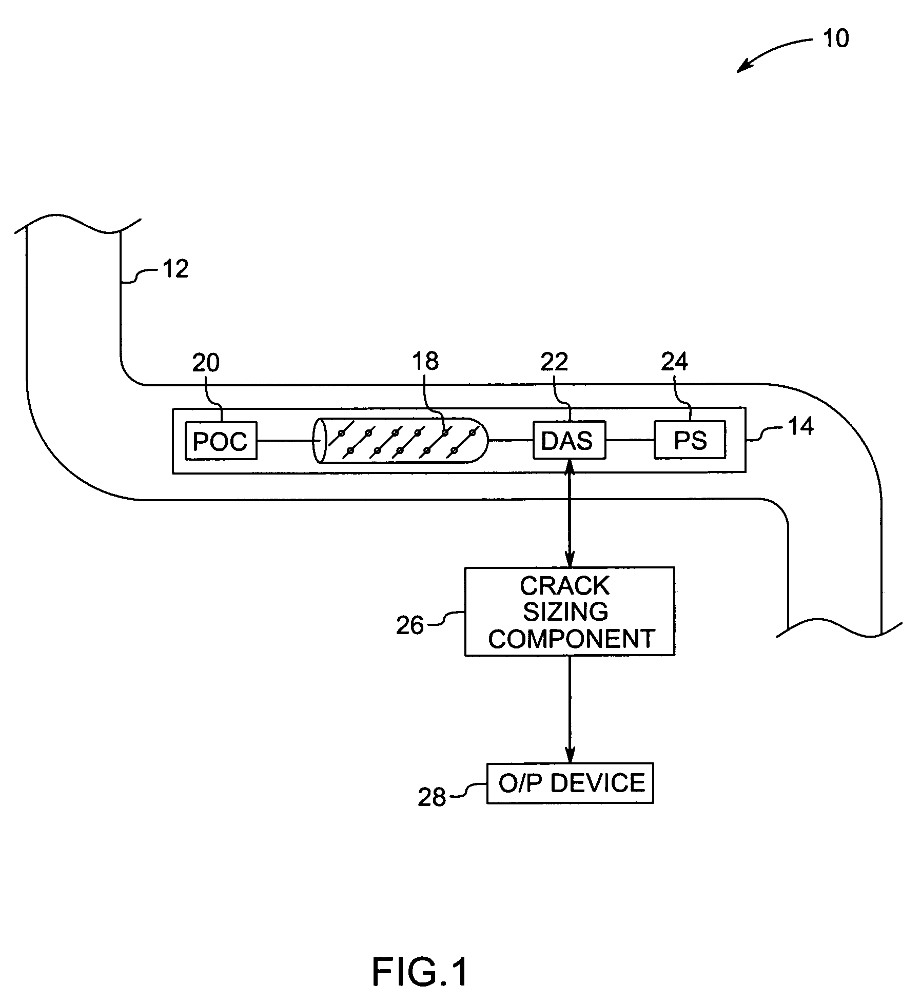
[0017]FIG. 1 is a block diagram showing a pipeline inspection system, designated generally by reference numeral 10. The pipeline inspection system 10 includes a pipeline 12 and a pipeline inspection gage (PIG) 14. The PIG 14 is a scanning device placed inside the pipeline and is typically used to find flaws such as cracks in the walls of the pipeline 12. The PIG 14 is transported through the length of the pipeline along with the fluid flow in the pipeline. The PIG is typically configured to send ultrasonic signals circumferentially in the pipeline walls and to receive reflected signals within ...


PUM

PropertyMeasurementUnit
depthaaaaaaaaaa
ultrasound scanaaaaaaaaaa
time of flightaaaaaaaaaa

Abstract

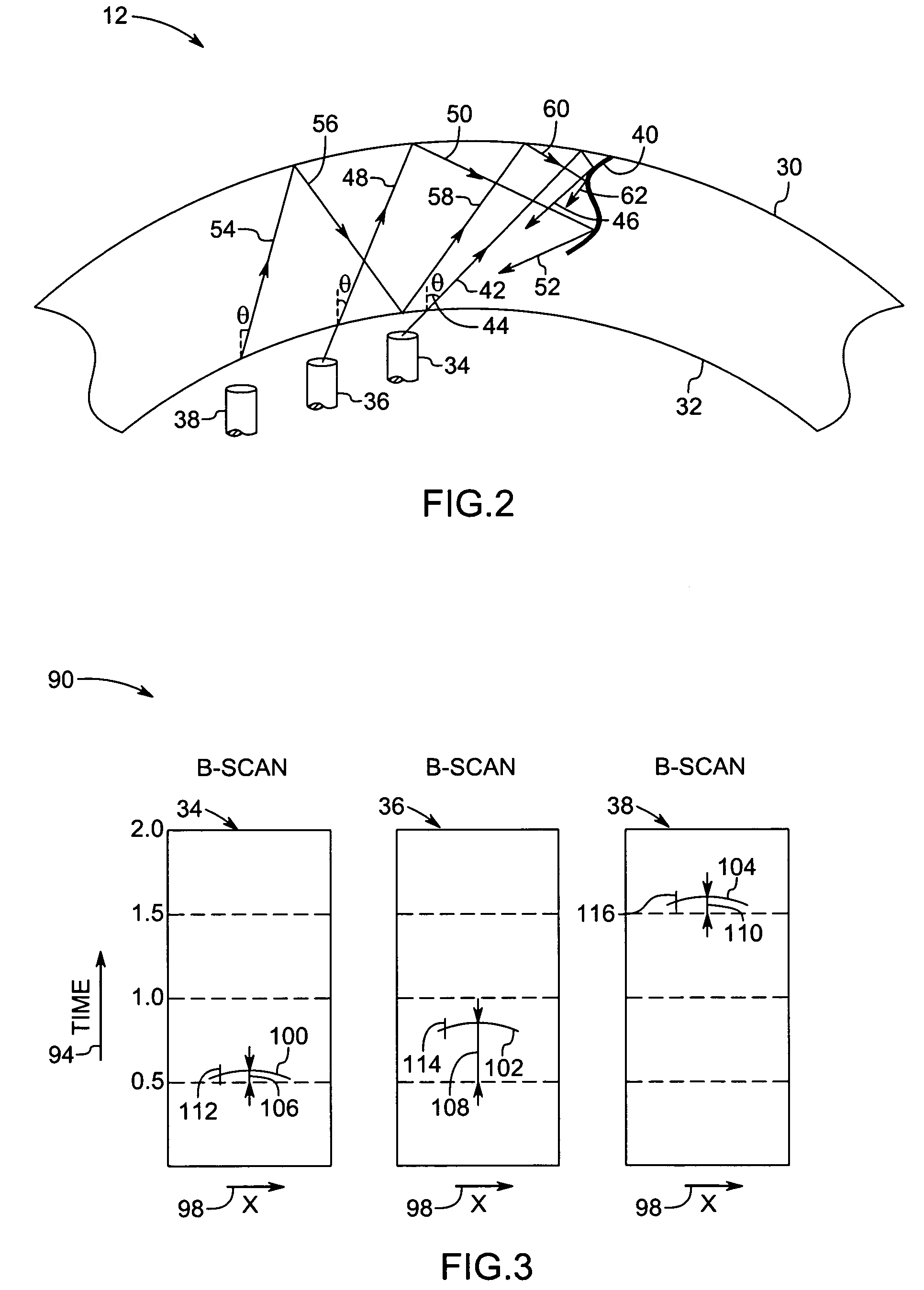
A method and apparatus for estimating a depth of a crack from ultrasound scan data are provided. The method includes mapping multiple amplitude responses from the ultrasound scan data, each mapped amplitude response being representative of a signal from one of the sensors. The method further includes locating multiple linear responses among the mapped amplitude responses, each linear response being an indicator of a reflected signal from the crack. One or more sensor that corresponds to the linear responses from a given crack is identified. The depth of the crack is estimated using data from the identified sensors.

Description

BACKGROUND[0001]The invention relates generally to inspection systems and particularly to pipeline inspection systems that use ultrasound data for detecting and sizing cracks and notches in pipelines.[0002]Pipelines that allow a large amount of material to be transported from one place to another are widely used in a variety of industries. A variety of fluids such as oil and / or gas are transported cheaply and efficiently using pipelines. Particulate matter, and other small solids suspended in fluids may also be transported through pipelines. Underground and underwater (deep sea) pipelines typically carry enormous quantities of oil and gas products that are important to energy-related industries, often under extreme conditions such as high pressure, high (or low) temperature and high flow rate.[0003]Flaws in constituent pipes may cause pipeline integrity degradation as the pipeline infrastructure ages. Corrosion or other pipeline defects can be caused by small spots of weakness, subs...

Claims


Application Information

Patent Timeline
Patent Type & Authority Patents(United States)
IPC IPC(8): G01N29/11
CPCG01N29/0645G01N29/069G01N29/07G01N29/11G01N29/343G01N29/4463G01N2291/2636G01N2291/0258G01N2291/0289G01N2291/0422G01N2291/044G01N2291/105
Inventor SIDDU, DINESH MYSOREDEWANGAN, SANDEEP KUMARKATRAGADDA, GOPICHANDRAMASWAMY, SIVARAMANIVAS
Owner GENERAL ELECTRIC CO
Learn More