
Vehicular navigation based on site specific sensor quality data

a technology of quality data and vehicle navigation, applied in the direction of distance measurement, eavesdropping prevention circuit, instruments, etc., can solve the problems of odometer to estimate, many location sensing devices subject to material errors, odometer to be subject to errors

Active Publication Date: 2007-11-20
DEERE & CO
View PDF7 Cites 66 Cited by
  • Summary
  • Abstract
  • Description
  • Claims
  • Application Information

AI Technical Summary

Benefits of technology

The patent describes a method and system for determining the location of a vehicle in a work area. The system uses both reception location data and optical location data to estimate the vehicle's position. The data processor selects the most accurate location data based on the estimated quality of the reception and optical signals. The technical effect of this patent is to provide a more accurate way to locate vehicles in a work area, which can improve safety and efficiency.

Problems solved by technology

Many location sensing devices are subject to errors (e.g., measurement error) in providing an accurate location estimate over time and different geographic positions.
Odometers are subject to material errors from slipping or sliding over a surface terrain.
For example, wheel or tire slippage may cause the odometer to estimate an erroneous location for a corresponding vehicle.
A Global Positioning System (GPS) may suffer from errors or lack of availability because one or more satellite transmissions are attenuated or reflected by buildings, trees, hills, terrain or other obstructions.
Vision based triangulation systems may experience error over certain angular ranges and distance ranges because of the relative position of cameras and landmarks.

Method used


Image

  • Vehicular navigation based on site specific sensor quality data
  • Vehicular navigation based on site specific sensor quality data
  • Vehicular navigation based on site specific sensor quality data

Examples


Embodiment Construction

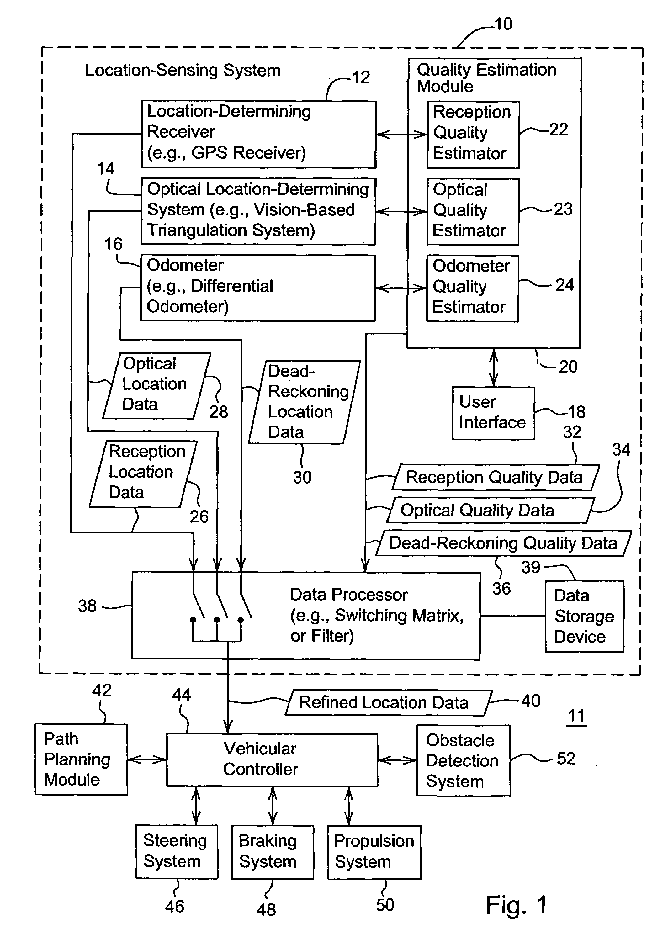
[0016]In accordance with one embodiment, FIG. 1 shows a system 11 for determining a location of a vehicle based on site specific sensor quality data. The system 11 comprises a location-sensing system 10 coupled to a vehicular controller 44. A path planning module 42 may provide a path plan or other navigation-related input data to the vehicular controller 44. The obstacle detection system 52 may provide navigation-related input on stationary or moving objects within a work area (e.g., to avoid collisions with such objects). In turn, the vehicular controller 44 may communicate with (e.g., issue control data or signals to) one or more of the following: a steering system 46, a braking system 48, and a propulsion system 50.

[0017]In one embodiment, the location sensing system 10 comprises a location-determining receiver 12, an optical location determining system 14, and a dead-reckoning system 16 that are coupled to a quality estimation module 20. The location determining receiver 12, th...


PUM


Abstract

A method and system for determining a location of a vehicle, the method comprises determining reception location data within a first cell of a work area for a vehicle. A reception quality estimator estimates reception quality data for the corresponding reception location data for the first cell. Optical location data is determined within a first cell of a work area for a vehicle. An optical quality estimator estimates optical quality data for the corresponding optical location data for the first cell. A data processor selects at least one of the reception location data and the optical location data as refined location data associated with the first cell based on the estimated reception quality data and estimated optical quality data.

Description

[0001]This document claims priority based on U.S. provisional application Ser. No. 60 / 655,544, filed Feb. 23, 2005, and entitled VEHICULAR NAVIGATION BASED ON SITE SPECIFIC SENSOR QUALITY DATA under 35 U.S.C. 119(e).FIELD OF THE INVENTION[0002]This invention relates to vehicular navigation based on site specific sensor quality data.BACKGROUND OF THE INVENTION[0003]Location sensing devices include odometers, Global Positioning Systems (GPS), and vision-based triangulation systems, for example. Many location sensing devices are subject to errors (e.g., measurement error) in providing an accurate location estimate over time and different geographic positions. The error in the location estimate may vary with the type of location sensing device. Odometers are subject to material errors from slipping or sliding over a surface terrain. For example, wheel or tire slippage may cause the odometer to estimate an erroneous location for a corresponding vehicle. A Global Positioning System (GPS) ...

Claims


Application Information

Patent Timeline
Patent Type & Authority Patents(United States)
IPC IPC(8): H04Q7/20G01C22/00
CPCH04L67/18G01C21/20H04L67/52
Inventor ANDERSON, NOEL WAYNE
Owner DEERE & CO
Learn More