
Print control system and medium

a control system and printing technology, applied in the field of printing technology, can solve the problems of inability to ignore the running cost that depends on the toner consumption, the enormous quantity of information printed by the printer, and the inability to so as to reduce the quantity of color materials such as toners and other wastes, and save the color materials within the range utilizable and usable to the user

Inactive Publication Date: 2007-11-20
FUJITSU LTD
View PDF9 Cites 29 Cited by
  • Summary
  • Abstract
  • Description
  • Claims
  • Application Information

AI Technical Summary

Benefits of technology

[0015]It is a primary object of the present invention, which was devised to obviate the problems inherent in the prior arts described above, to efficiently reduce a spent quantity of color materials such as toners in a way that restrains a decline of print quality.
[0021]According to another aspect of the present invention, a print control system for controlling a print of print target data containing color specifying information comprises an information input module inputting information on a difference from a coloring value based on the color specifying information, and a color adjusting module (13, 14, 15, 16, 17) adjusting a mix of color materials on the basis of the color specifying information within a range of the difference, and minimizing a consuming quantity of the color materials. The color adjusting module (13, 14, 15, 16, 17) may adjust the mix of the color materials in such a direction as to reduce a consuming quantity of the color material.
[0025]Further, the present invention schemes to minimize the consuming quantity of the color materials within the range of the difference between the coloring values inputted, and is therefore capable of saving the color materials within the range utilizable and usable to the user.
[0026]As discussed above, according to the present invention, the spent quantity of the color materials such as toners etc can be efficiently reduced in a way that restrains a decline of a print quality.

Problems solved by technology

Then, an enormous quantity of information is printed by printers.
The color print involves especially a large quantity of toner consumption.
Accordingly, a running cost that depends upon the toner consumption is not ignorable nowadays.
These prior arts, however, have no scheme of distinguishing between categories of the print data such as characters, graphic, images etc, and the toner save is carried out by the same method with respect to all pieces of print data.
Then, as a result, the toner save function described above proved poor of a print quality and was therefore unusable except at a print level for trial.
The prior art 1 is effective in, for example, the characters and graphics with no expression of halftones (intermediate colors), but raises a problem of being unable to functioning effectively in the characters and graphics involving the expressions of images and halftones.
This is because it is difficult to extract the outline of the character and graphic containing the halftone expression.
Further, the prior art 2 also has problems in a pattern having a periodicity in the print data and in a dot pattern.
For attaining this share-turnabout, a print cost per page is a bottleneck.
A cost for using the toners for a color print is higher than a cost for a monochrome print.
Therefore, the print of such data involves a further increase in toner spent quantity.
On the other hand, if a large quantity of prints can be attained owing to a decrease in price of the main unit of the printer product, there might be a strict request for a running cost in terms of purchasing the printer product.

Method used


Image

  • Print control system and medium
  • Print control system and medium
  • Print control system and medium

Examples


first embodiment

[0044]A printing system in a first embodiment of the present invention will hereinafter be discussed with reference to FIGS. 1 through 9. According to the first embodiment, the printing system for providing a toner save function when printing will be explained.

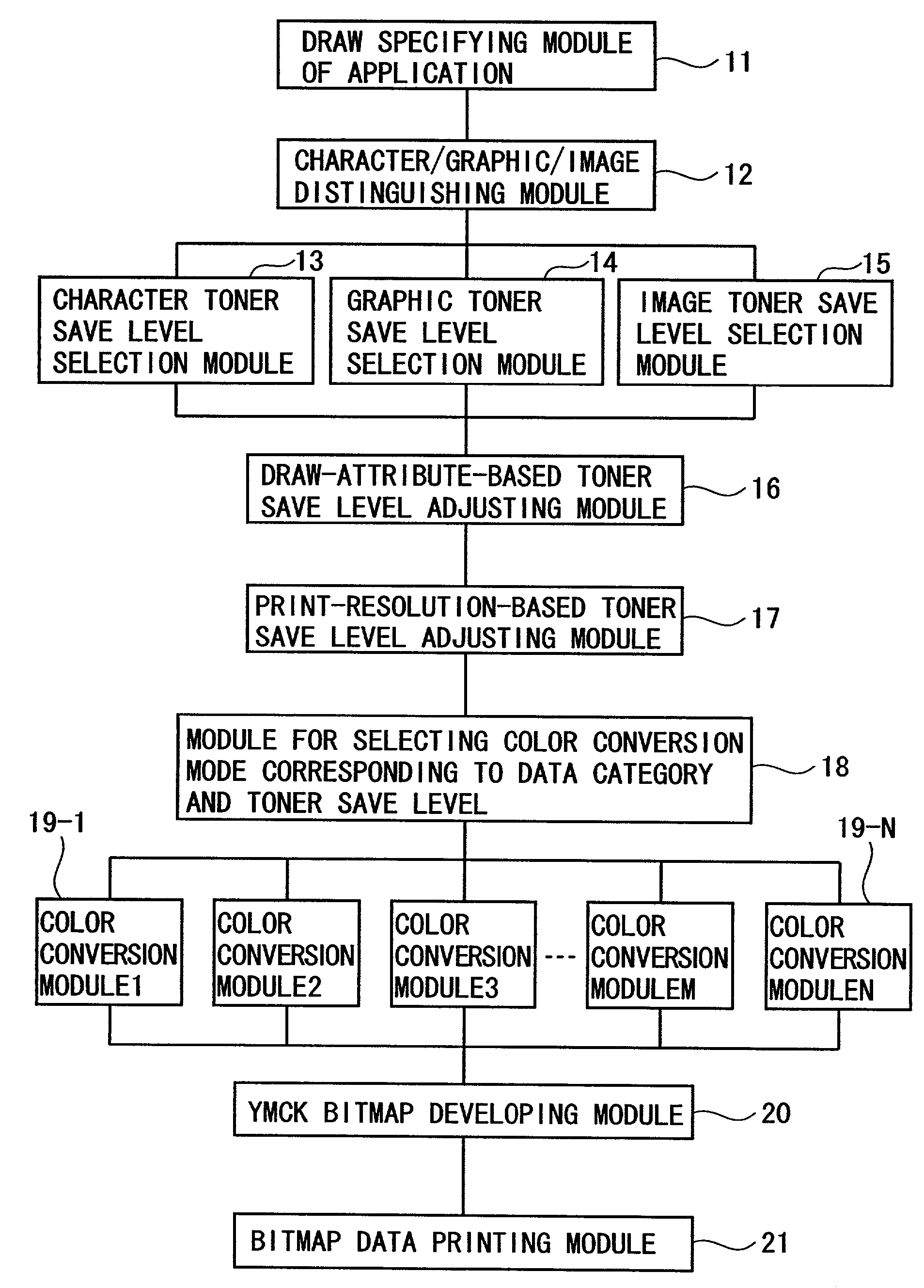
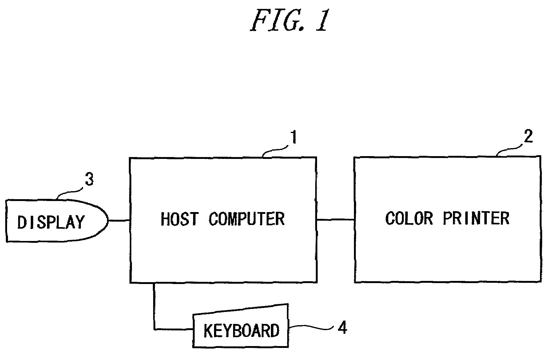
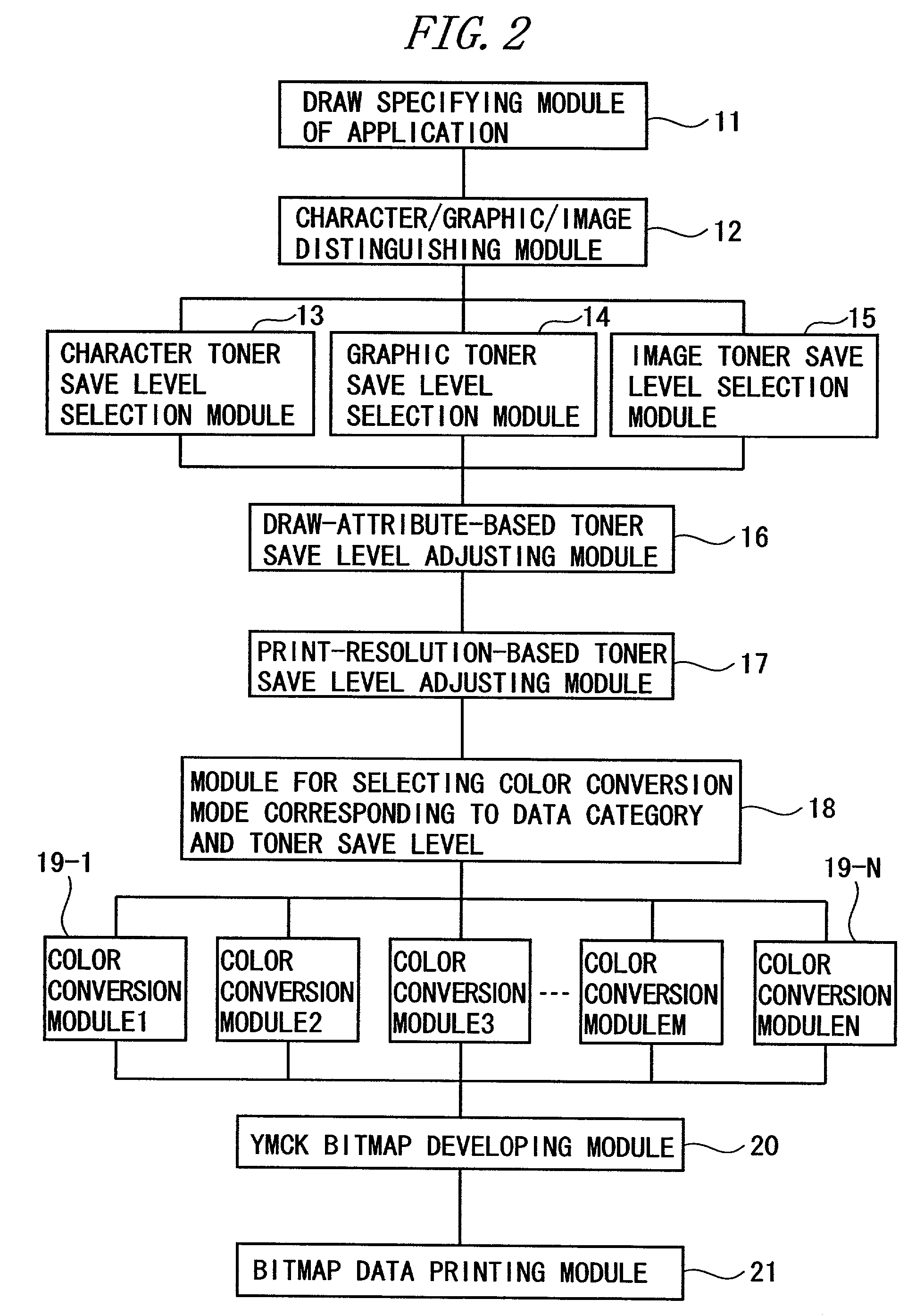
[0045]FIG. 1 is a diagram showing an example of system architecture of this printing system. FIG. 2 is a diagram showing an architecture of functions of this printing system. FIG. 3 shows an example of a menu screen displayed on a display 3 shown in FIG. 1. FIG. 4 shows an example of one of lookup tables for color conversions based on toner save levels. FIG. 5 is a diagram showing a structure of a selection table for selecting the lookup table shown in FIG. 4. FIG. 6 is a flowchart showing a toner save process in the first embodiment. FIG. 7 is a flowchart showing details of a lookup table determination process for characters shown in FIG. 6. FIG. 8 is a flowchart showing details of a lookup table determination process for gra...

second embodiment

[0133]The printing system in a second embodiment of the present invention will hereinafter be described with reference to FIGS. 10 through 14.

[0134]FIG. 10 is a diagram showing a data structure of a lookup table for the color conversion based on the toner save levels in the second embodiment. FIG. 11 is a diagram showing a data structure of a lookup table for a character-attribute-based color conversion in this printing system. FIG. 12 is a diagram showing a data structure of a lookup table for a graphic-attribute-based color conversion. FIG. 13 is a diagram showing a data structure of a lookup table for a print-resolution-based color conversion. FIG. 14 is a flowchart showing a toner save process in the second embodiment.

[0135]The discussion in the first embodiment has focused on the printing system in which one of the lookup tables shown in FIG. 4 is selected in accordance with the selection table (FIG. 5), and the conversion from RGB into YMCK is carried out.

[0136]The discussion ...

third embodiment

[0172]The printing system in a third embodiment of the present invention will hereinafter be described with reference to FIGS. 15 and 16.

[0173]FIG. 15 shows an example of a setting screen for specifying an allowable color difference when printing in the third embodiment. FIG. 16 is a flowchart showing a lookup table creating process for performing the toner save within a range of the allowable color difference.

[0174]The printing system discussed in the first and second embodiments is that the toner save is executed based on what is specified by the user on the menu screen shown in FIG. 3, and that one of the lookup tables illustrated in FIG. 4 is selected in accordance with the selection table (FIG. 5), and the conversion from RGB into YMCK is carried out.

[0175]What will be discussed in the third embodiment is the printing system for executing the toner save within an allowable color difference range specified by the user. Other configurations and operations in this printing system ...


PUM


Abstract

A print control system for controlling a print of print target data containing color specifying information includes a data distinguishing module (12) for distinguishing between pieces of element data contained in the print target data, and a color adjusting module (13, 14, 15, 16, 17) for adjusting a mix of color materials based on the color specifying information according to a category of the element data.

Description

BACKGROUND OF THE INVENTION[0001]The present invention relates to a printing technology.[0002]With sophisticated information processing technologies, a multiplicity of information devices are used in a variety of scenes in the society. Then, an enormous quantity of information is printed by printers. Particularly over the recent years, images captured by digital cameras etc are printed by color printers in the great majority of cases. The color print involves especially a large quantity of toner consumption.[0003]Accordingly, a running cost that depends upon the toner consumption is not ignorable nowadays. This being the case, a scheme for saving the toners has hitherto been proposed.[0004]What is known as a toner save technology for this purpose is a method of extracting an outline of character / graphic data after being developed on, e.g., a bitmap memory. This method serves to restrain a quantity of toners by diminishing a dot size of an internal area or the outline of the characte...

Claims


Application Information

Patent Timeline
Patent Type & Authority Patents(United States)
IPC IPC(8): G06K15/00B41J29/38B41J2/525G03G15/01G06K15/12G06T1/00H04N1/46H04N1/60
CPCG06K15/129G06K2215/0074
Inventor SUGIMOTO, MORIAKI
Owner FUJITSU LTD
Learn More