
Image capturing apparatus

Inactive Publication Date: 2007-11-20
KONICA MINOLTA INC
View PDF7 Cites 3 Cited by
  • Summary
  • Abstract
  • Description
  • Claims
  • Application Information

AI Technical Summary

Benefits of technology

[0016]Since the first drive speed control value set as a value which lies within the structural resonance changed of the image capturing apparatus among the plurality of drive speed control values is changed so that drive time of the first driver based on the first drive speed control value becomes shorter and the first driver is driven, while suppressing noise caused by resonance, the image capturing direction of the apparatus can be changed at high speed.
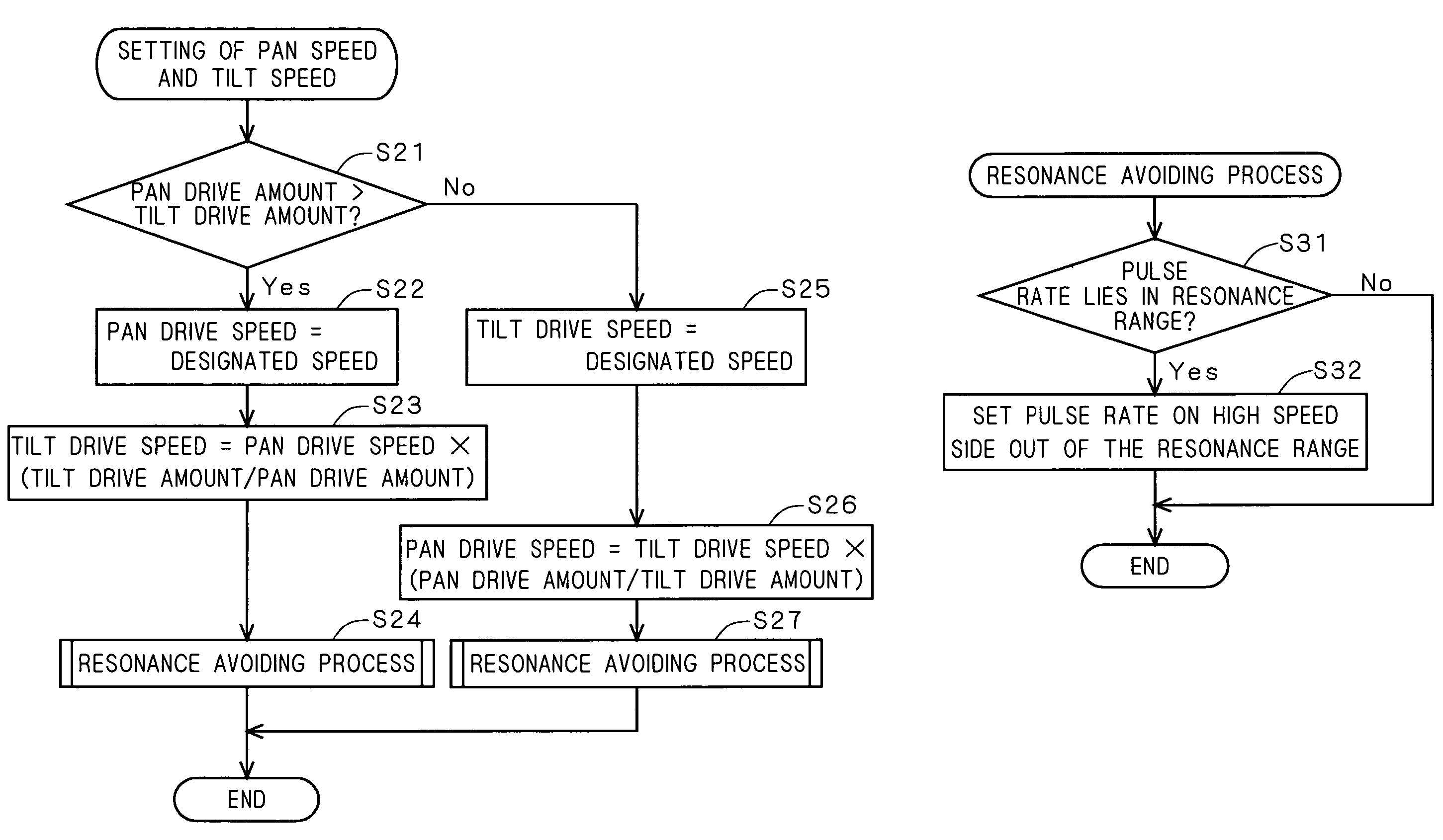
[0018]At the time of changing the image capturing direction only by a designated amount by changing the relative angle of the image capturing part to the image capturing apparatus body by the first and second drivers, in the case where the conditions are satisfied that the first drive amount of the first driver is smaller than the second drive amount of the second driver and the first drive speed control value for the first driver is a value within the structural resonance range of the image capturing apparatus, the first drive speed control value is changed to an alternative value out of the resonance range and the first driver is driven only by the first drive amount in the drive period of the second driver. Thus, while suppressing noise caused by resonance, the image capturing direction of the apparatus can be changed at high speed.
[0021]Therefore, an object of the present invention is to provide a technique capable of changing the image capturing direction of an image capturing apparatus at high speed while suppressing noise caused by resonance.

Problems solved by technology

When the changing speed of the image capturing direction is too fast, it is difficult to perform an accurate operation.
In the operation method of the latter type, however, in order to change the image capturing direction to the target direction as fast as possible, when a pulse rate is simply changed, depending on the changing direction of the image capturing direction, the pulse rate given to one of the two pulse motors may enter the resonance frequency range and it causes large noise sound at the time of changing of the image capturing direction.
However, since the resonance which generates during changing of the image capturing direction due to the motor itself is larger than the resonance which generates due to the gear, only by the countermeasure of suppressing the resonance which generates due to the gear like the above-described noise preventing technique, generation of the resonance during changing of the image capturing direction, that is, generation of noise cannot be sufficiently suppressed.

Method used


Image

  • Image capturing apparatus
  • Image capturing apparatus
  • Image capturing apparatus

Examples


Embodiment Construction

[0038]Hereinafter, embodiments of the present invention will be described with reference to the drawings.

Outline of Surveillance Camera System

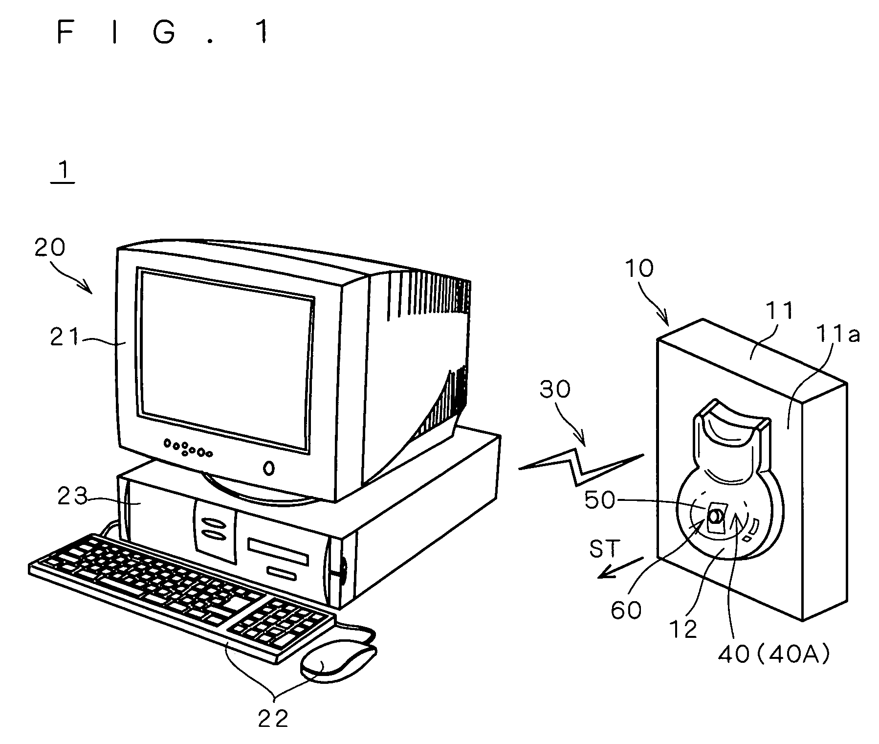
[0039]FIG. 1 is a diagram showing an outline of a surveillance camera system 1 as an example of an image capturing apparatus according to an embodiment of the present invention.

[0040]The surveillance camera system 1 has a surveillance camera 10 and a controller 20 for controlling the surveillance camera 10.

[0041]The surveillance camera 10 mainly has a housing 11, a transparent cover 12 constructed by a combination of an almost semi-spherical portion and an almost semi-cylindrical portion, and a camera unit 50 covered with the transparent cover 12.

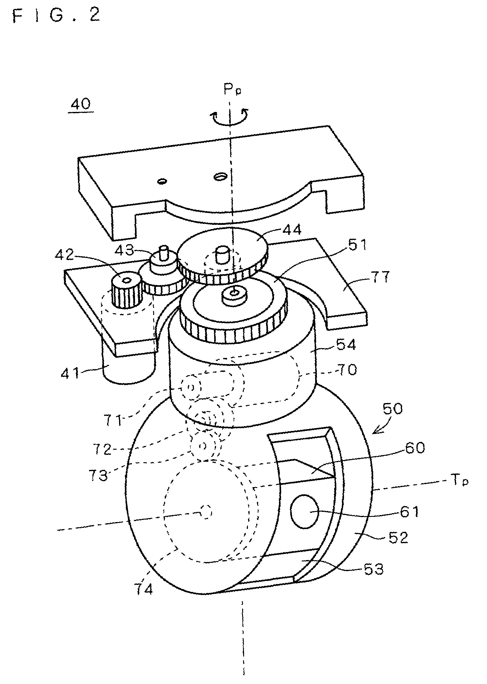
[0042]The camera unit 50 has an image capturing unit 60 for acquiring image data of a subject, and a driving mechanism (hereinafter, referred to as “swing mechanism”) 40 for changing the image capturing direction (the direction of the optical axis of the taking lens) of the image capturing unit 60.

[00...


PUM


Abstract

The present invention provides a technique capable of changing the image capturing direction of a camera at high speed while suppressing noise generated by resonance. At the time of changing the angle of the image capturing direction of a surveillance camera from a base angle to a first angle, if driving of both of a motor for panning and a motor for tilting is simply started simultaneously and completed simultaneously, there is a case such that the motor for panning generates resonance with the body of the surveillance camera or the like and noise becomes too loud. In such a case, the drive speed of the motor for panning, that is, the pulse rate is shifted to a high speed side on which resonance does not generate and the panning is finished first. Specifically, the angle of the image capturing direction is changed from the base angle to a second angle and, after that, changed from the second angle to the first angle.

Description

[0001]This application is based on application No. 2003-182778 filed in Japan, the contents of which are hereby incorporated by reference.BACKGROUND OF THE INVENTION[0002]1. Field of the Invention[0003]The present invention relates to an image capturing apparatus capable of changing its image capturing direction in a state where a body of the image capturing apparatus is fixed.[0004]2. Description of the Background Art[0005]Since a surveillance camera used by being mounted on the wall, the ceiling or the like of a room has to monitor a wide range, usually, the image capturing direction of the camera can be freely changed by the driving of various motors or the like by a remote control or the like.[0006]Conventionally, such a surveillance camera is turnable around two axes of the horizontal axis and the vertical axis. For example, in the case of using a pulse motor as a drive source for turning the camera around each of the horizontal and vertical axes, by controlling the turn amount...

Claims


Application Information

Patent Timeline
IPC IPC(8): H04N5/228G03B15/00G03B17/00G08B13/196H04N5/222H04N5/225H04N5/232H04N7/18
CPCG08B13/1963H04N7/183H04N5/232H04N23/661H04N23/695
Inventor TERAMOTO, TOUGOSATO, JUNJI
Owner KONICA MINOLTA INC
Learn More