
Circuits for circuit interrupting devices having automatic end of life testing function

a circuit interrupting device and testing function technology, applied in the direction of circuit-breaking switches, circuit device connections, protective switch details, etc., can solve the problems of users' false sense of security, no longer being able to provide ground fault protection, and cutting off electricity

Inactive Publication Date: 2007-11-13
HUANG HUADAO
View PDF26 Cites 66 Cited by
  • Summary
  • Abstract
  • Description
  • Claims
  • Application Information

AI Technical Summary

Benefits of technology

Ensures the circuit interrupting device can only be reset when components function properly, preventing false reassurances and potential electric shocks by automatically detecting end-of-service-life conditions and displaying status indicators, thus enhancing user safety.

Problems solved by technology

According to the UL standards under 934A effective Jul. 28, 2006, a GFCI is required not only to have reverse wiring protection, but also to be able to provide a user with indications to alert the user when the GFCI has reached the end of its service life and is no longer capable of providing ground fault protection.
That is because for most of the GFCIs currently available on the market, when their service life ends, resetting by pressing the reset button is still possible, which gives the users a false sense of security that they are still under proper protection of the GFCI, while in fact the GFCIs' capability of sensing a ground fault and cutting off the electricity due to a ground fault has been compromised.
Thus, when a ground fault occurs, the GFCI is unable to provide any protection, which can result in fatal electric shocks.

Method used


Image

  • Circuits for circuit interrupting devices having automatic end of life testing function
  • Circuits for circuit interrupting devices having automatic end of life testing function
  • Circuits for circuit interrupting devices having automatic end of life testing function

Examples


Embodiment Construction

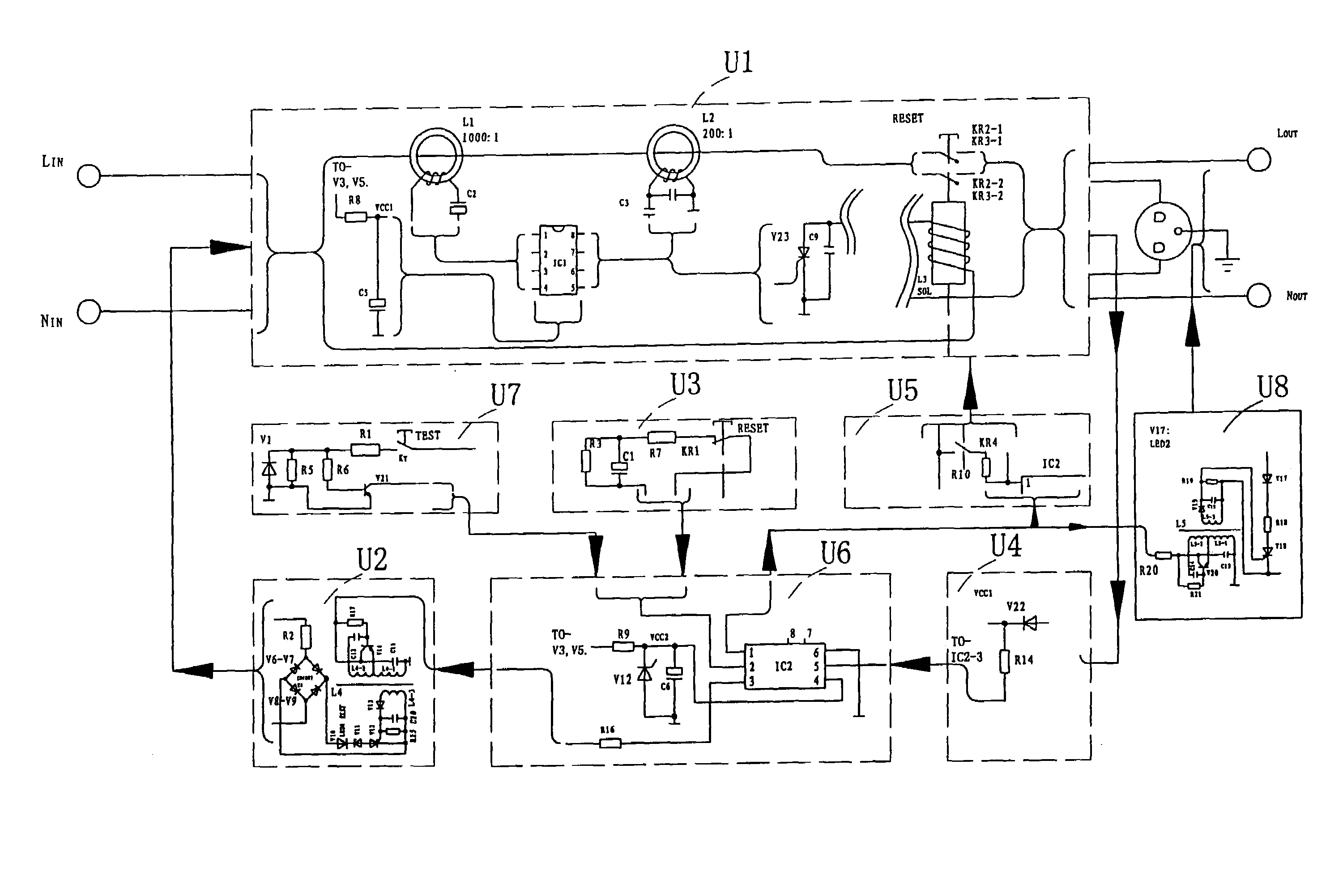
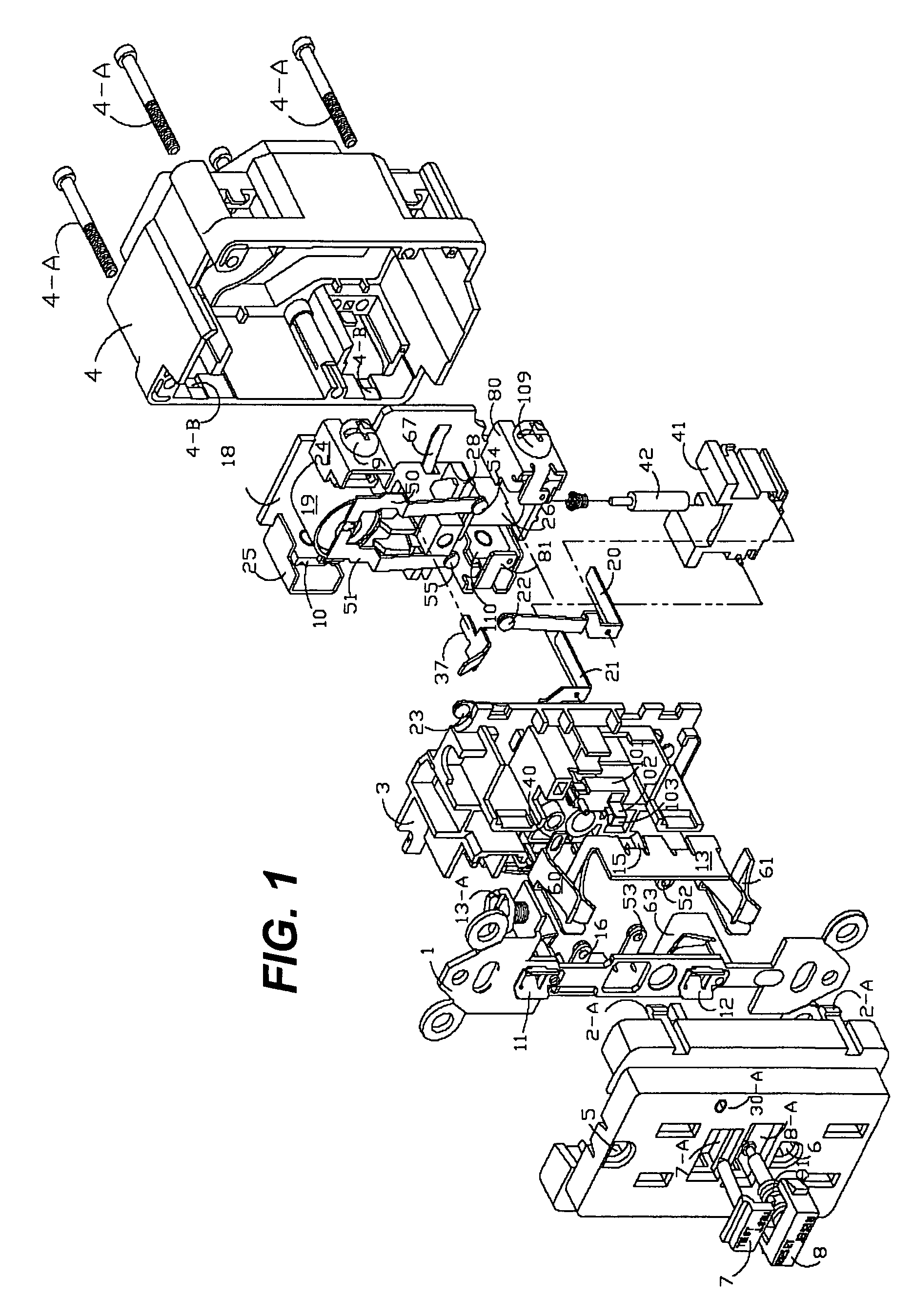
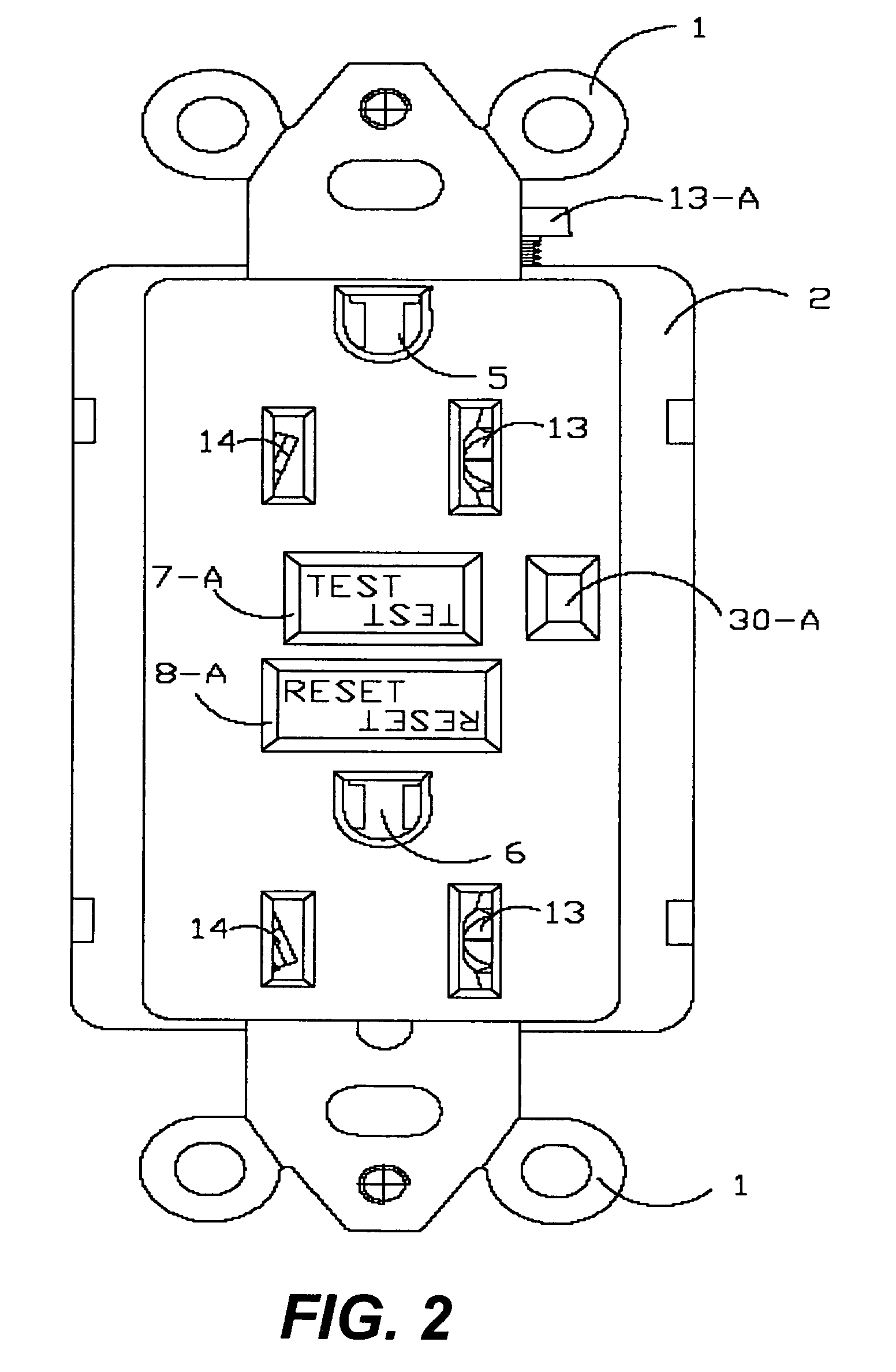
[0042]The present invention describes a circuit interrupting device, which includes, but is not limited to, a ground fault circuit interrupter (GFCI), an arc fault circuit interrupter (AFCI), an immersion detection circuit interrupter, an appliance leakage circuit interrupter, or a circuit breaker. The preferred circuit interrupting device is a GFCI.

[0043]The following experimental designs and result are illustrative, but not limiting the scope of the present invention. Reasonable variations, such as those occur to reasonable artisan, can be made herein without departing from the scope of the present invention. Also, in describing the invention, specific terminology is employed for the sake of clarity. However, the invention is not intended to be limited to the specific terminology so selected. It is to be understood that each specific element includes all technical equivalents which operate in a similar manner to accomplish a similar purpose.

[0044]FIG. 1 illustrates an exemplary ci...


PUM


Abstract

The present invention provides a set of circuits which is capable of performing an automatic check on main components of a circuit interrupting device when the circuit interrupting device is properly powered and the device is at a tripped state to determine whether these main components function normally. The results of the automatic check can be detected by depressing a reset button in the circuit interrupting device. If the reset button can be depressed, the main components function normally. Alternatively, the results can be automatically displayed by a showing on the face lid of the circuit interrupting device of either a green light, which means that the main components function normally, or a red or yellow light or no light, which means that at least one of the main components in the circuit interrupting device does not function properly. The present invention also provides an end-of-service-life detection integrated circuit chip capable of receiving and transmitting an automatic check signal and determining whether or not the circuit interrupting device can be reset. The preferred circuit interrupting device is a ground fault circuit interrupter (GFCI).

Description

RELATED APPLICATIONS[0001]The present application is a Continuation-In-Part (CIP) of U.S. patent application Ser. No. 11 / 437,811, filed on May 22, 2006, which is a CIP of U.S. patent application Ser. No. 11 / 362,037, filed on Feb. 27, 2006 now U.S. Pat. No. 7,195,500, which claims the priority of U.S. Provisional Patent Application Ser. No. 60 / 656,090, filed on Feb. 25, 2005, which are herein incorporated by reference.FIELD OF THE INVENTION[0002]The present invention relates to a set of circuits capable of performing an automatic check on main components in a circuit interrupting device when the device is powered on and at a tripped state to determine whether these main components function normally. The results of the automatic check can be detected by depressing a reset button in the circuit interrupting device. If the reset button can be depressed, the main components function normally. Alternatively, the results can be automatically displayed by a showing on the face lid of the ci...

Claims


Application Information

Patent Timeline
Patent Type & Authority Patents(United States)
IPC IPC(8): H02H7/00
CPCH01H83/04H01R13/7135H01H2071/044H01R13/652H01R2103/00H01R24/78H01R13/6691
Inventor HUANG, HUADAOHUAYANG, LU
Owner HUANG HUADAO
Learn More