
Noisy clock test method and apparatus

a technology of noise clock and test method, applied in the field of electronic devices, can solve the problems of external clock, noise common cause, and thus the operation of electronic devices, and achieve the effects of reducing the noise of external clocks

Inactive Publication Date: 2007-11-06
POLARIS INNOVATIONS LTD
View PDF2 Cites 2 Cited by
  • Summary
  • Abstract
  • Description
  • Claims
  • Application Information

AI Technical Summary

Problems solved by technology

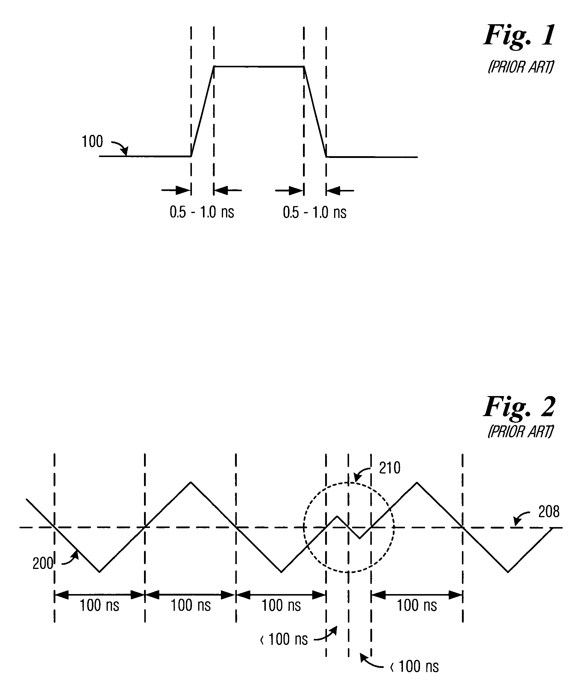
This can be particularly troublesome when the system clock is designed to operate at faster rates, such as a 7.5 ns or a 2.5 ns clock for 133 MHz and 400 MHz designs, respectively.
The reliance on a reference voltage makes the external clock, and thus the electronic device operations, more susceptible to noise.
Noise is commonly caused by other electronic devices that are being tested in parallel.
Furthermore, the noise generated by the other DRAM devices being tested may cause noise on the external clock.
The noise on the external clock frequently causes the clock to transition early.
These shorter cycle times may cause the device under test to fail.

Method used


Image

  • Noisy clock test method and apparatus
  • Noisy clock test method and apparatus
  • Noisy clock test method and apparatus

Examples


Embodiment Construction

[0023]The making and using of the presently preferred embodiments are discussed in detail below. It should be appreciated, however, that the present invention provides many applicable inventive concepts that can be embodied in a wide variety of specific contexts. The specific embodiments discussed are merely illustrative of specific ways to make and use the invention, and do not limit the scope of the invention.

[0024]The present invention will be described with respect to preferred embodiments in a specific context, namely the testing of a DRAM device. The invention may also be applied, however, to other electronic devices, such as other memory devices, processors, digital signal processors, access devices, and other electronic devices utilizing a clock signal.

[0025]It is further noted that, unless indicated otherwise, all functions described herein may be performed in either hardware or software, or some combination thereof. In a preferred embodiment, however, the functions are per...


PUM


Abstract

A clock filter for use in filtering an external clock signal to create an internal clock signal for use by an electronic device is provided. The clock filter receives the external clock signal and sets the internal clock signal high when the external clock signal is above a first threshold and sets the internal clock signal low when the external clock signal is below a second threshold. The clock filter holds the internal clock signal constant for a period of time after the clock transitions.

Description

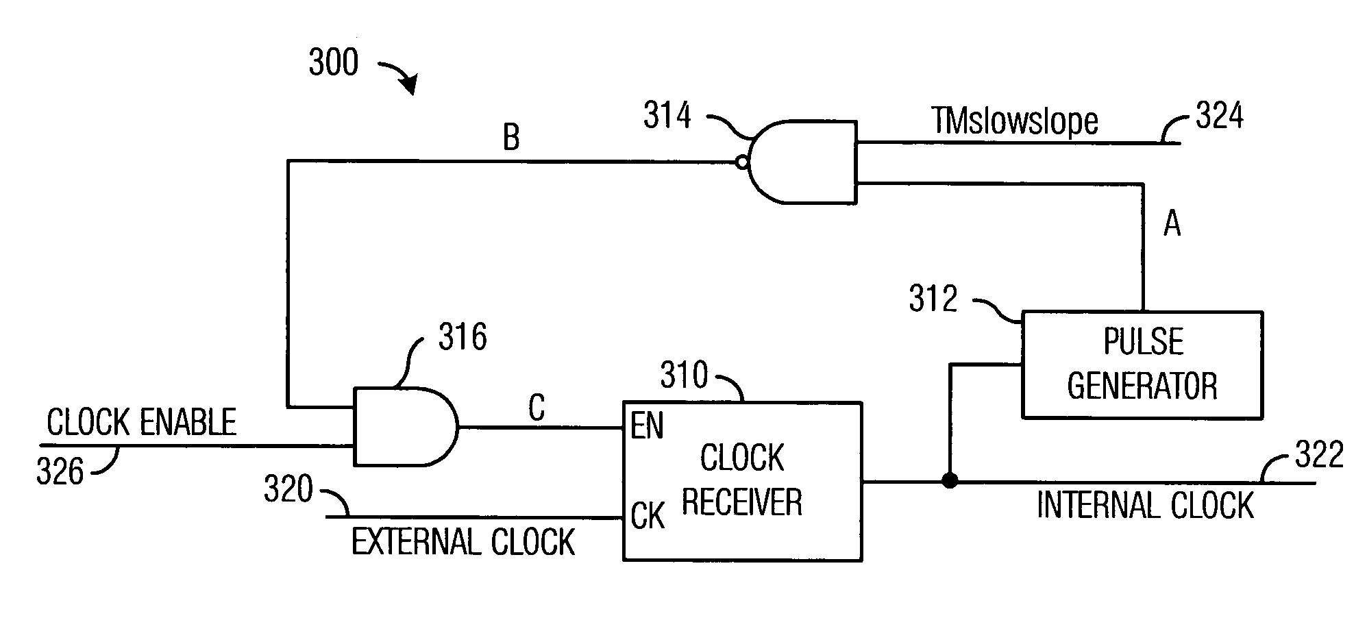
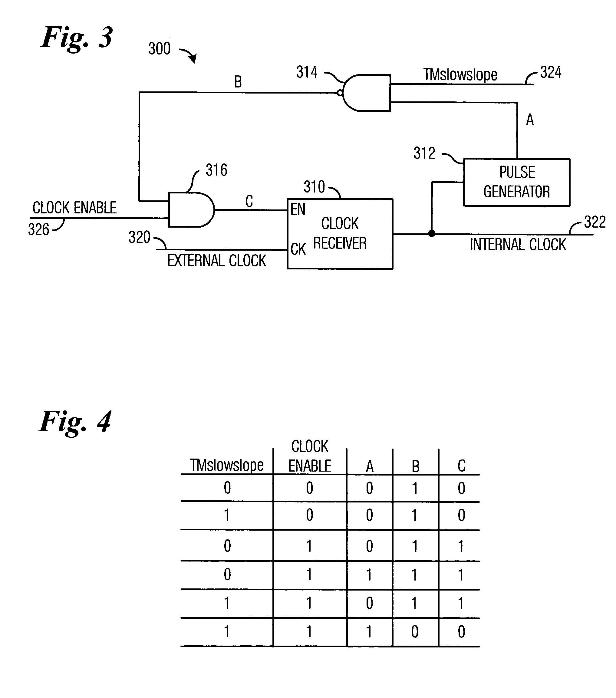
TECHNICAL FIELD[0001]The present invention relates generally to electronic devices, and more particularly to electronic devices using an external clock.BACKGROUND[0002]Electronic devices are frequently driven by a clock signal. The clock signal provides a timing signal that causes electronic components to perform specific actions. For example, clock signals are frequently used by logic circuits to control the timing of reads and writes to memory devices, such as dynamic random access memory (DRAM), static random access memory (SRAM), electrically-erasable programmable read-only memory (EEPROM), read-only memory (ROM), and the like.[0003]Ideally, the clock signal has sharp transition edges, i.e., the clock signal transitions from a low state to a high state quickly and transitions from a high state to a low state quickly. FIG. 1 illustrates one example of a preferred clock signal 100 that transitions from low-to-high within about 0.5-1.0 ns and transitions from high-to-low within abo...

Claims


Application Information

Patent Timeline
Patent Type & Authority Patents(United States)
IPC IPC(8): G06F1/04G06F1/00G06F1/12H03K19/00H03K19/096H03K5/12H03K5/1252
CPCH03K5/1252H03K5/12
Inventor VOGELSANG, THOMAS
Owner POLARIS INNOVATIONS LTD
Learn More