
Fluid flow measuring and proportional fluid flow control device

a technology of proportional fluid flow and measuring fluid, which is applied in the direction of process control, speed/acceleration/shock measurement, instruments, etc., can solve the problems of destroying the pattern formed on the wafer, reprocessing, and discarded or reprocessing of the wafer, so as to achieve greater stability

Active Publication Date: 2007-11-06
ENTEGRIS INC
View PDF6 Cites 17 Cited by
  • Summary
  • Abstract
  • Description
  • Claims
  • Application Information

AI Technical Summary

Benefits of technology

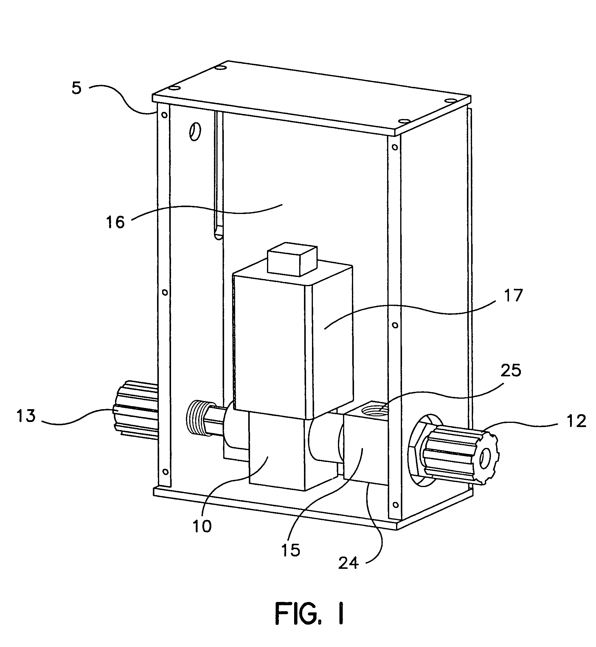
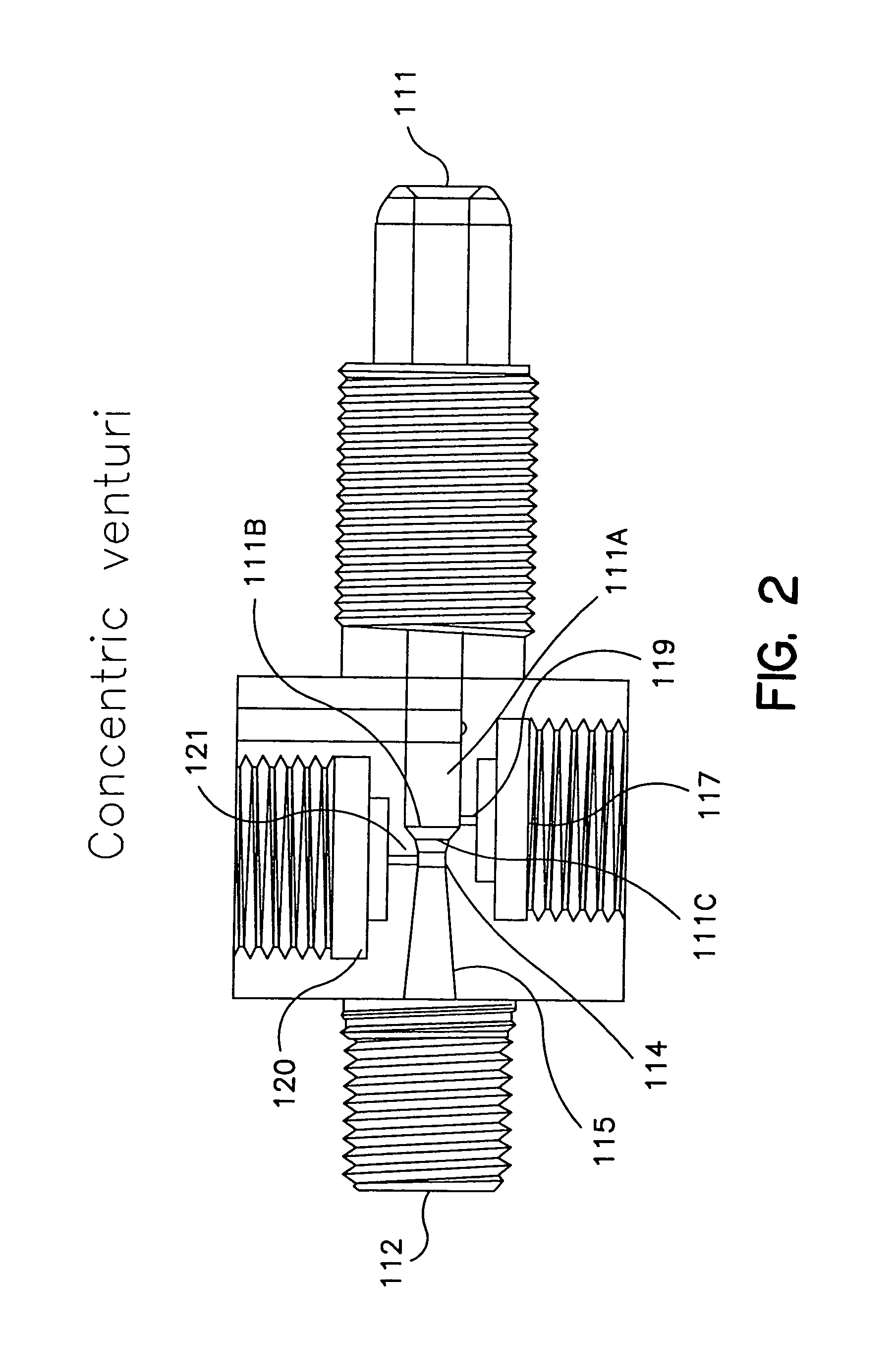
[0008]The problems of the prior art have been overcome by the present invention, which provides a fluid flow measuring and proportional fluid flow control device. The device controls fluid flow using a proportioning valve in response to a pressure loss measured in a flow restriction element. Pressure is sensed at or near the inlet and at or near the outlet of the restrictive flow element, and the resulting pressure drop therebetween is converted to a flow rate of the fluid being controlled. The pressure drop can be continually or continuously monitored, and one or more valves modulated to obtain the desired flow rate. The control system has applicability to fluids having a wide range of viscosities, it being capable of accurately and repeatably dispensing such fluids with minimal operator involvement. It offers accurate and repeatable performance in a cost-effective and flexible manner, responding quickly to real-time process variations. In a preferred embodiment, the design of the pressure drop element allows recovery of most of the pressure loss due to the restrictive element.
[0012]Embodiments of the present invention provide an advantage over prior art PID controllers, because it can provide greater stability.
[0013]Embodiments of the present invention provide an advantage over prior art PID controllers, because it can be used over a greater set of operating conditions because the fuzzy logic can be programmed to account for changes in operating environment.

Problems solved by technology

This can destroy the pattern being formed on the wafer, requiring that the wafer be discarded or reprocessed.
The coating of larger wafers (e.g., 300 mm in diameter and larger) is also problematic, as turbulence issues arise.
However, this approach creates turbulent air flow over the wafer and can result in uneven or nonuniform coatings.
Reducing the spin speed with larger wafers reduces the turbulence at the surface of the wafer, but can introduce new problems.
With the reduced speed, the fluid moves across the wafer more slowly, and thus spreading the fluid to the wafer edge before the fluid begins to setup or dry becomes an issue.
However, the pumps suitable for such applications are expensive and require frequent replacement due to excessive wear.

Method used


Image

  • Fluid flow measuring and proportional fluid flow control device
  • Fluid flow measuring and proportional fluid flow control device
  • Fluid flow measuring and proportional fluid flow control device

Examples


example 1

[0069]This example illustrates the use of an embodiment of the present invention to measure and control liquid flow to enable the delivery of discrete volumes of fluid for chemical mechanical planarization substrate processing. More specifically, this example illustrates how an embodiment of the present invention may be used to measure and control liquid flow to enable the delivery of discrete volumes of a polishing fluid to a substrate. Chemical mechanical polishing is useful in the manufacture of optical lenses. Chemical mechanical planarization is useful in the manufacture of semiconductor devices. Polishing fluids may be acidic or basic and may contain abrasives such as silica or alumina. A fluid useful for polishing silicon dioxide includes silica slurry in an aqueous potassium hydroxide solution; a fluid useful for polishing copper metal includes an oxidizer such as hydrogen peroxide, an inhibitor such as benzotriazole, and an aqueous solution of an organic acid such as acetic...

example 2

[0071]This example illustrates the use of an embodiment of the present invention to measure and control liquid flow so that discrete volumes of liquid precursors can be delivered to a vaporizer to form a gas. More specifically, this example illustrates how an embodiment of the present invention may be used to measure and control the flow of liquid precursors to a vaporizer.

[0072]Liquid precursors are chemicals that are heated in a vaporizer to form a gas. The gas is then delivered to a heated substrate in a reaction chamber where it is further decomposed or reacts on the substrate. The gas may be used to form a thin film of a metal, a semiconductor, or a dielectric on the substrate (chemical vapor deposition or atomic layer chemical vapor deposition processes). It also can be used to etch the surface of a substrate, or it can be used to dry the substrate. Liquid precursors may be pure liquids such as water, 2-propanol, or tetraethyl orthosilicate, TEOS. Liquid precursors may also co...

example 3

[0075]This example illustrates the use of an embodiment of the present invention to measure and control liquid flow to enable the delivery of fluid to a substrate for electroless plating. More specifically, this example illustrates how an embodiment of the present invention can be used to measure and control liquid flow to enable the dispense of a series of chemicals onto a substrate to form a metal film in plating processes. Such a process eliminates drag out of chemicals common to bath plating processes. Solutions of metals and metal alloys useful for plating include, but are not limited to, silver, copper, platinum, palladium, gold and tin. Catalysts are often required to activate the substrates to the plating solution. These catalysts include colloidal palladium, carbon, graphite, tin-palladium colloids, and conductive polymers like polypyrrole. The precious metals in some of these catalysts and plating solutions are expensive and waste during the plating process needs to be min...


PUM


Abstract

The present invention provides restrictive-flow flow measurement devices, valve improvements and signal control devices and processes that control the flow of liquids, including control processes for single-liquid calibration.

Description

CROSS-REFERENCE TO RELATED APPLICATION[0001]This application claims priority under 35 USC 119 to PCT Application No. PCT / US03 / 022533, filed Jul. 18, 2003, entitled “FLUID FLOW MEASURING AND PROPORTIONAL FLUID FLOW CONTROL DEVICE,” which claims priority from U.S. Provisional Application Ser. No. 60 / 397,053, filed Jul. 19, 2002, entitled “LIQUID FLOW CONTROLLER AND PRECISION DISPENSE APPARATUS AND SYSTEM” and 60 / 397,162, filed Jul. 19, 2002, entitled “FLUID FLOW MEASURING AND PROPORTIONAL FLUID FLOW CONTROL DEVICE,” the disclosures of which are hereby incorporated by reference. The present application relates to U.S. patent application Ser No. 09 / 991,392, filed Nov. 16, 2001, issued as U.S. Pat. No. 6,527,862, entitled “FLOW CONTROLLER,” which is a divisional application of U.S. patent application Ser. No. 09 / 488,146, filed Jan. 20, 2000, issued as U.S. Pat. No. 6,348,098, entitled “FLOW CONTROLLER,” both of which claim priority from U.S. Provisional Application Ser. No. 60 / 116,511, f...

Claims


Application Information

Patent Timeline
Patent Type & Authority Patents(United States)
IPC IPC(8): G06F19/00G01P5/14G01F1/44G05D7/06
CPCG01F1/363G01F1/44G06N7/02G01F25/0007G05D7/0635G01F1/50G01F25/10G01F1/34G01P5/14
Inventor WARGO, CHRISTOPHERNIERMEYER, J. KARLSHYU, JIEH-HWABRODEUR, CRAIG L.BASSER, WILLIAM
Owner ENTEGRIS INC
Learn More