Data input devices and methods for detecting movement of a tracking surface by a laser speckle pattern

a data input device and laser technology, applied in computing, instruments, electric digital data processing, etc., can solve the problems of devices that cannot devices that still require one moving part, cursor to skip, devices that lack the ability to track on any surface, etc., and achieve the effect of stable speckle pattern

Inactive Publication Date: 2007-11-06
MICROSOFT TECH LICENSING LLC
View PDF36 Cites 33 Cited by
  • Summary
  • Abstract
  • Description
  • Claims
  • Application Information

AI Technical Summary

Benefits of technology

[0010]In accordance with another aspect of the present invention, a data input device for use with a tracking surface having light-scattering properties comprises a substantially coherent light source generally as set forth above. A detector associated with the substantially coherent light source defines a plane for detecting scattered substantially coherent light. An optic collects at least a portion of the substantially coherent light beam scattered by the tracking surface and alters a wavefront profile of the collected scattered light beam so that the collected scattered light beam has a substantially constant phase relative to the plane of the detector, such that the detector detects a substantially stable speckle pattern from the collected scattered light beam.
[0011]In accordance with still another aspect of the present invention, a method comprises projecting a substantially coherent light beam from a data input device onto a tracking surface having light-scattering properties. The tracking surface scatters the substantially coherent light beam when the substantially coherent light beam strikes the tracking surface. The method guides the substantially coherent light beam toward the tracking surface with an optic and spaces the tracking surface from the optic by a distance sufficient to inhibit any substantial retro-reflection of the substantially coherent light beam striking optic from striking the detector. The method further detects out-of-phase substantially coherent light reflected from the tracking surface as a speckle pattern and utilizes the detected speckle pattern to track relative movement between the device and the tracking surface.

Problems solved by technology

But such devices lack the ability to track on any surface, requiring a suitable frictional interface between the ball and the surface.
Moreover, these devices still require one moving part, the ball.
In addition, aliasing artifacts may cause the cursor to skip, rather than move fluidly during rapid motion of the device.
Although such devices are able to eliminate the moving ball, they are less universal by requiring a specific tracking surface to operate.
However, smooth or glossy surfaces may prove difficult to track upon, because they may generate no shadows from texture and present a low contrast image that may not provide adequate features upon which to track.
Such systems suffer from several drawbacks.
For example, such systems do not track the actual location information relating to the location of the user's moving hand and finger with respect to the device, but instead merely rely upon merely directional information to indicate the direction of cursor movement on the display and force information to indicate the proportional speed of cursor movement on the display.
These systems may be difficult to use for some users because they function solely on direction and force information, rather than position information, as is typical with a standard mouse, with which most users are accustomed and may find more intuitive.
In addition, such systems may suffer from cursor drift, wherein no finger engages the post, but one or more of the force sensors incorrectly senses a pressure.
Cursor drift is undesirable because the cursor moves across the display, without direction by the user.

Method used


Image

  • Data input devices and methods for detecting movement of a tracking surface by a laser speckle pattern
  • Data input devices and methods for detecting movement of a tracking surface by a laser speckle pattern
  • Data input devices and methods for detecting movement of a tracking surface by a laser speckle pattern

Examples


Embodiment Construction

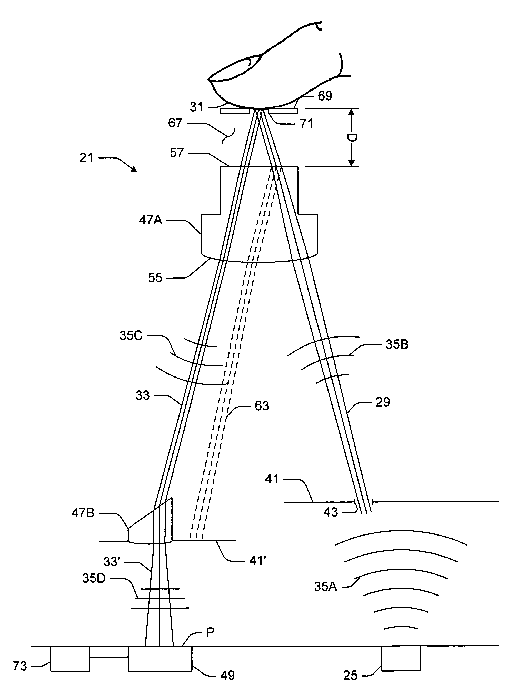
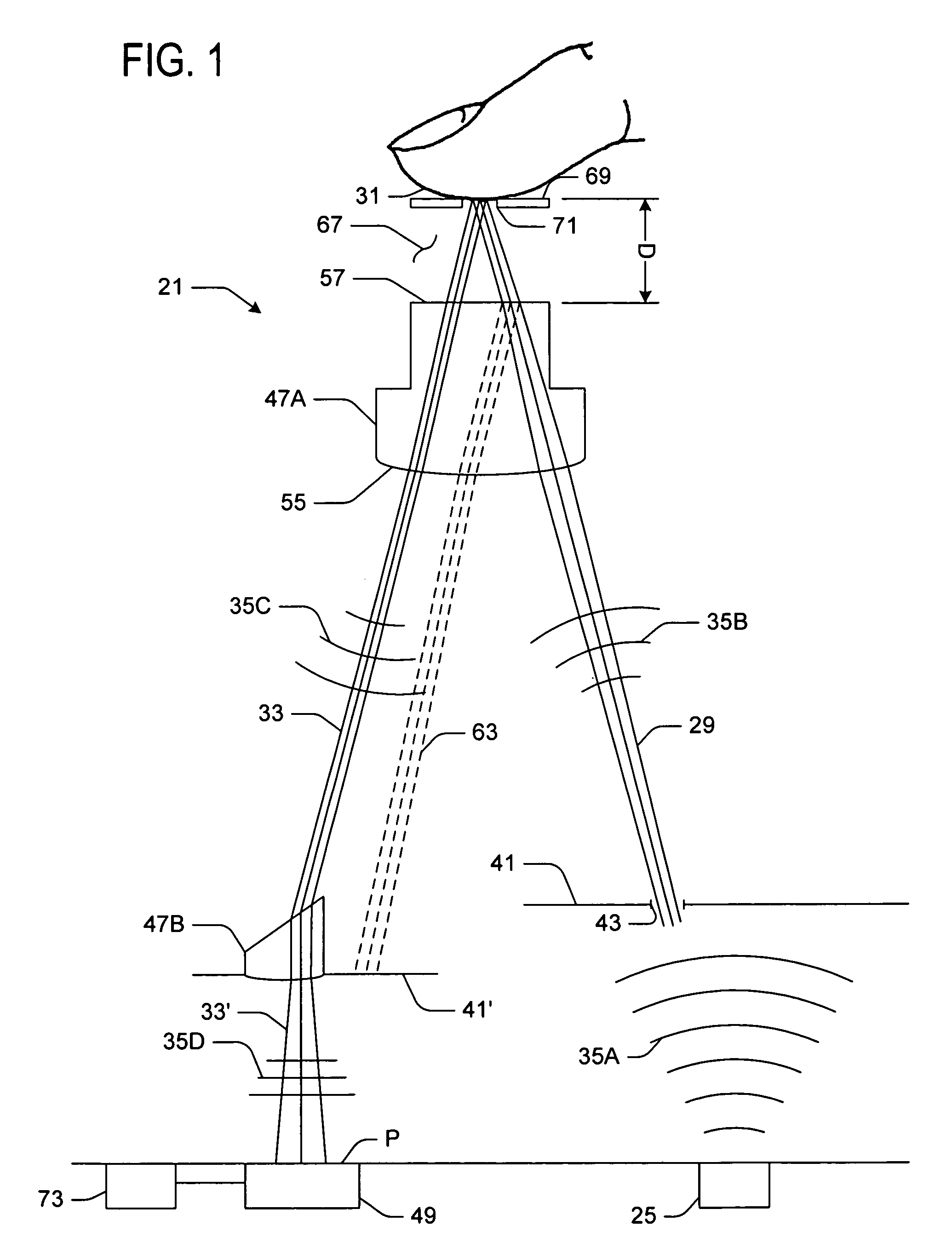
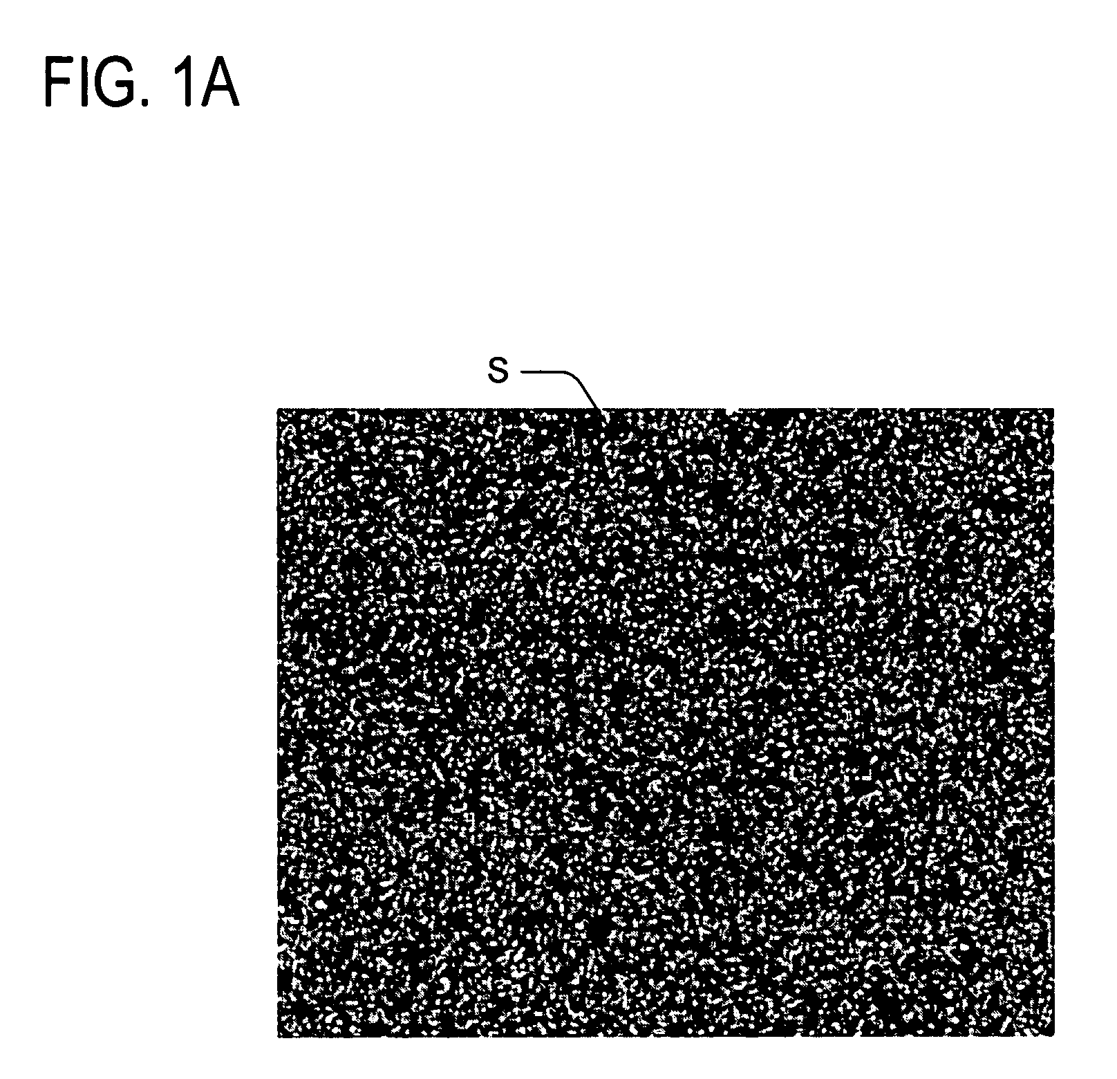
[0023]In one embodiment, the invention includes a data input device for use with a tracking surface that is optically rough, or in other words, has light-scattering properties, to track relative movement between the device and the tracking surface. FIG. 1 is a schematic of such a data input device and tracking surface of the present invention. The data input device, generally indicated 21, includes a substantially coherent light source 25 (e.g., a laser) for projecting a substantially coherent light beam, generally indicated 29. The substantially coherent light beam projects onto a tracking surface 31 during operation of the device 21. The tracking surface 31 scatters the substantially coherent light beam 29 striking the tracking surface as a scattered light beam 33, as will be discussed in greater detail below. Because the tracking surface 31 has light scattering properties, the substantially coherent light scattered from the tracking surface produces a speckle pattern S (e.g., FIG...


PUM


Abstract

A data input device for use with an optically rough tracking surface comprising a substantially coherent light source for projecting a substantially coherent light beam onto the tracking surface for scattering the substantially coherent light beam. An optic guides the projected substantially coherent light beam toward the tracking surface and comprises a first boundary facing the substantially coherent light source and a second boundary opposite the first boundary. A detector detects at least a portion of the scattered light beam comprising a speckle pattern. The optic is arranged such that the tracking surface is spaced from the second boundary by a distance sufficient to inhibit any substantial retro-reflection of the substantially coherent light beam striking the second boundary from striking the detector. A controller responsive to the detector operates the device in a tracking mode for utilizing the detected speckle pattern to track relative movement between the device and the tracking surface. The device is particularly useful in handheld and laptop devices, such as personal digital assistants, cellular phones, laptop computers, etc., where it is desirable to interact with a tracking surface comprising human skin, such as a fingertip.

Description

TECHNICAL FIELD[0001]Embodiments of the present invention relate to the field of computer input devices, and particularly data input devices, such as a mouse, trackball, joystick, touch pad, or a touch-sensitive post. In particular, embodiments of this invention relate to data input devices for projecting a substantially coherent light beam onto a tracking surface having light-scattering properties, guiding the substantially coherent light beam toward the tracking surface with an optic, orienting and spacing the tracking surface from the optic by a distance sufficient to inhibit any substantial retro-reflection, detecting laser speckle (i.e., out of phase substantially coherent light) reflected from the tracking surface, and utilizing the detected speckle pattern to track relative movement between the device and the tracking surface.INCORPORATION BY REFERENCE[0002]The following U.S. patent is hereby fully incorporated by reference: U.S. Pat. No. 6,531,692 B1 issued to Adan et al., e...

Claims


Application Information

Patent Timeline
Patent Type & Authority Patents(United States)
IPC IPC(8): G09G5/00G06F3/033G06F3/042
CPCG06F3/0421
Inventor RANTA, CRAIG S.LUTIAN, JOHN M.
Owner MICROSOFT TECH LICENSING LLC
Why Eureka
Try Eureka