
Data input device for tracking and detecting lift-off from a tracking surface by a reflected laser speckle pattern

a data input device and laser speckle technology, applied in computing, instruments, electric digital data processing, etc., can solve the problems of inability to track on any surface, device lack of accuracy or intermittent cursor tracking, device still requires one moving part, etc., and achieve the effect of stable speckle pattern for tracking

Inactive Publication Date: 2007-06-05
MICROSOFT TECH LICENSING LLC
View PDF43 Cites 17 Cited by
  • Summary
  • Abstract
  • Description
  • Claims
  • Application Information

AI Technical Summary

Benefits of technology

The patent describes a data input device that uses a tracking surface and a coherent light source to track movement between the device and the surface. The device includes an optic that alters the wavefront profile of the coherent light beam to create a stable speckle pattern on the surface. The device can detect and track the speckle pattern to determine relative movement between the device and the surface. The device can also suspend tracking when the device is separated from the surface by a certain distance. The technical effects of this invention include improved accuracy and stability in data input and the ability to track and suspend tracking without the need for additional sensors.

Problems solved by technology

Because such devices have a moving ball that must pass through a hole in the housing, such devices often become contaminated with dust and dirt, which may yield inaccurate or intermittent cursor tracking.
Thus, a major limitation of such a device is that it requires a tracking surface with particular characteristics, such as adequate friction and cleanliness, which are not readily found on all surfaces.
However, such devices lack the ability to track on any surface, requiring a suitable frictional interface between the ball and the surface.
Moreover, these devices still require one moving part, the ball.
In addition, aliasing artifacts may cause the cursor to skip, rather than move fluidly.
Although such devices are able to eliminate the moving ball, they are less universal by requiring a specific tracking surface to operate.
However, smooth surfaces with little color variation may prove difficult to track upon.
Smooth surfaces generate no shadows from texture and present a low contrast image that may not provide adequate features upon which to track.
Surfaces with very little color variation also present a low contrast image that may not provide adequate features upon which to track.
However, these systems lack the ability to both track movement of a tracking surface over substantially any surface and detect when the device has been removed from the tracking surface for freezing the cursor.

Method used


Image

  • Data input device for tracking and detecting lift-off from a tracking surface by a reflected laser speckle pattern
  • Data input device for tracking and detecting lift-off from a tracking surface by a reflected laser speckle pattern
  • Data input device for tracking and detecting lift-off from a tracking surface by a reflected laser speckle pattern

Examples


Embodiment Construction

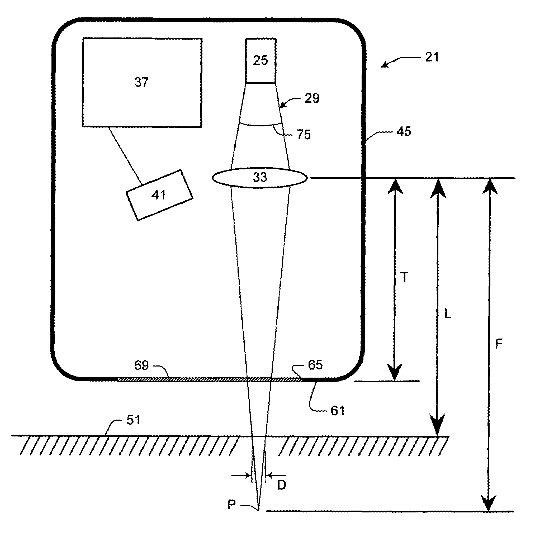
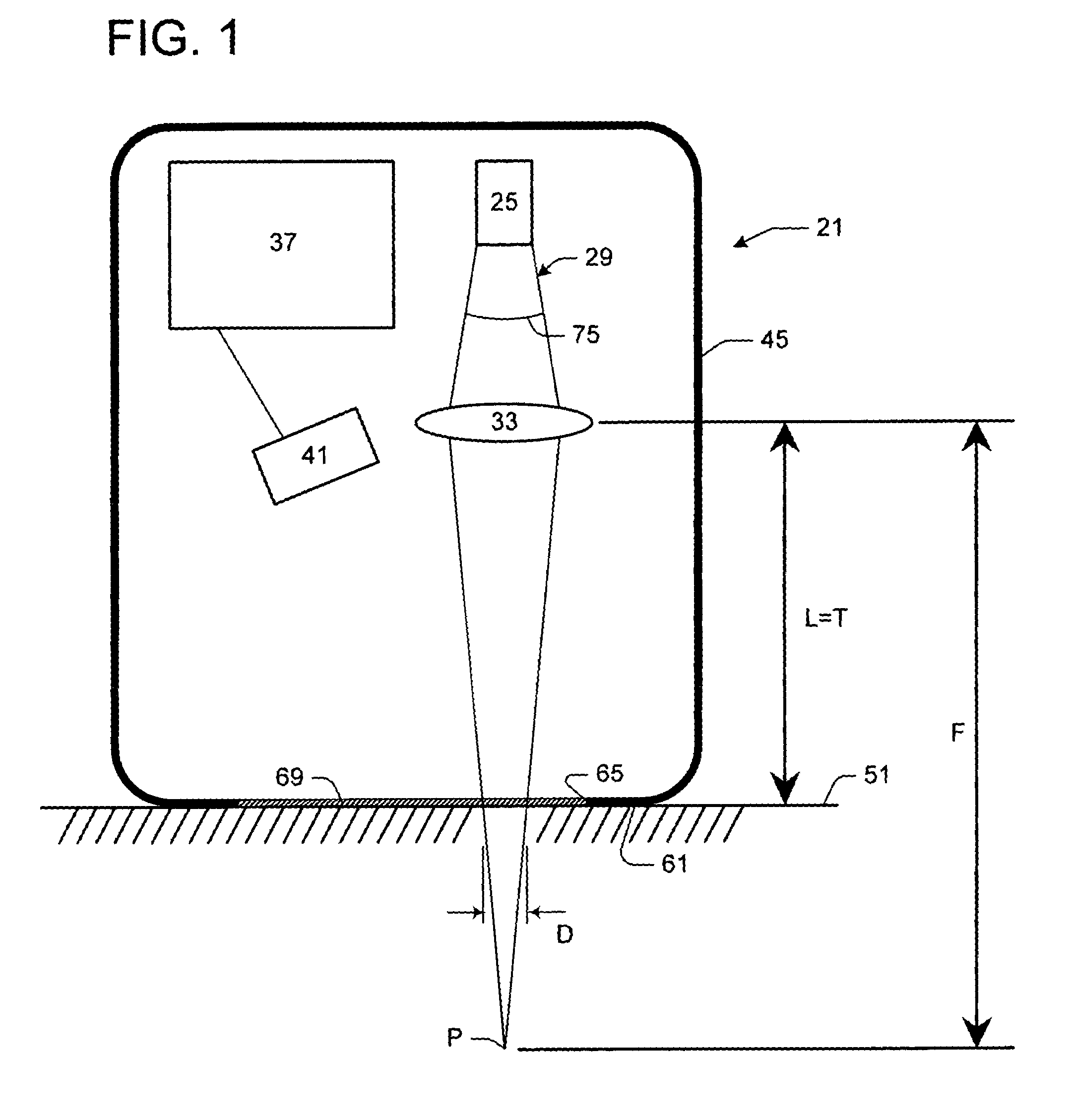
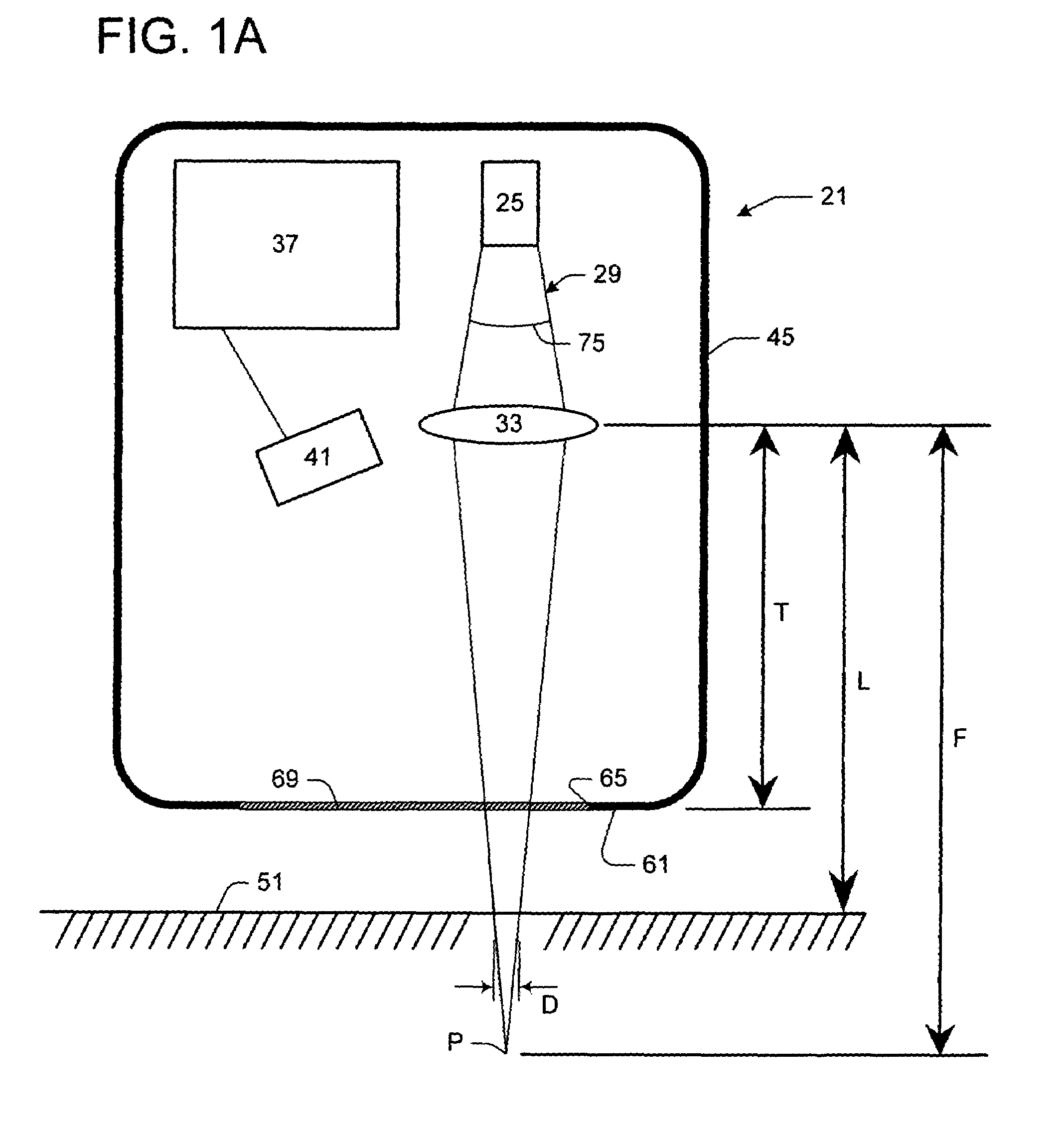
[0025]In one embodiment, the invention includes a data input device for use with a tracking surface that is optically rough, or in other words, has light-scattering properties. FIG. 1 is a schematic of a data input device of the present invention. The data input device, generally indicated 21, includes a coherent light source 25 (e.g., a laser) for projecting a coherent light beam, generally indicated 29. An optic 33, a controller 37, or tracking engine, and a detector 41 are each enclosed in a housing 45 of the device 21. The data input device 21 is used with a tracking surface 51 to track relative movement between the device and the tracking surface. The tracking surface 51 is optically rough, so that coherent light reflected from the tracking surface produces a speckle pattern 53 (e.g., FIG. 2). For example, paper, wood, metal, fabric, plastic and human skin each generally have sufficient surface variation to reflect a speckle pattern 53. Only surfaces that are perfectly reflecti...


PUM


Abstract

A data input device for use with an optically rough tracking surface comprising a coherent light source projecting a coherent light beam and an optic positioned in the coherent light beam. The optic alters a wavefront profile of the coherent light beam so that the coherent light beam has a substantially constant phase relative to a plane perpendicular to the beam at a tracking distance from the optic. The coherent light beam is projected onto the tracking surface to reflect a substantially stable speckle pattern. A controller responsive to a detector correlates the substantially stable speckle pattern to track relative movement between the coherent light beam and the tracking surface. The controller suspends tracking of relative movement between the coherent light beam and the tracking surface when the detector detects a boiling speckle pattern.

Description

TECHNICAL FIELD[0001]Embodiments of the present invention relate to the field of computer input devices, and particularly data input devices, such as a mouse or optical pen, employing coherent light striking a tracking surface. In particular, embodiments of this invention relate to data input devices for projecting a coherent light beam onto the tracking surface and altering a wavefront profile of the coherent light beam so that the coherent light beam has a substantially constant phase relative to a plane perpendicular to the beam at a tracking distance from the optic for reflecting a substantially stable speckle pattern from the altered coherent light beam.INCORPORATION BY REFERENCE[0002]The following U.S. patent is hereby fully incorporated by reference: U.S. Pat. No. 6,531,692 B 1 issued to Adan et al., entitled “OPTICAL COUPLING ASSEMBLY FOR IMAGE SENSING OPERATOR INPUT DEVICE”, and assigned to Microsoft Corporation.BACKGROUND OF THE INVENTION[0003]Previous computer input devic...

Claims


Application Information

Patent Timeline
Patent Type & Authority Patents(United States)
IPC IPC(8): G09G5/08G06F3/033G06F3/042
CPCG06F3/0317G06F3/03547G06F3/042G06F2203/0338G06F3/0304G06F3/03543
Inventor LUTIAN, JOHN MICHAEL
Owner MICROSOFT TECH LICENSING LLC
Learn More