
Synchronizing position detecting circuit

Inactive Publication Date: 2007-10-23
LAPIS SEMICON CO LTD
View PDF4 Cites 1 Cited by
  • Summary
  • Abstract
  • Description
  • Claims
  • Application Information

AI Technical Summary

Benefits of technology

[0007]The present invention may provide a synchronizing position detecting circuit for setting a window size that can securely capture a pilot signal even when a distance between a base station and a mobile station changes due to movement of the mobile station during a sleep time.

Problems solved by technology

However, in the mobile station in the mobile communication system employing the intermittent reception system, since the reception processing is once stopped during the sleep time, it is impossible to track the phase of the spreading code of the base station during the sleep time, and thus it is difficult to immediately produce a spreading code in phase with the spreading code of the base station at the start of the next reception term.
However, since a slight error exists in the normal synchronizing code generator, the phase of the spreading code produced by the synchronizing code generator deviates from the correct phase with a lapse of the sleep time, for example.
Thus, the pilot signal can not be captured after the lapse of the sleep time.
In the foregoing pilot signal capturing circuit (synchronizing position detecting circuit), however, there has been a problem that since the window size is set only taking into account the phase shift of the synchronizing code based on the error of the synchronizing code generator, it can not deal with a phase shift of the synchronizing code caused by a change in distance between the base station and the mobile station due to movement of the mobile station during the sleep time, and thus there are those instances where the pilot signal can not be detected within the set window.

Method used


Image

  • Synchronizing position detecting circuit
  • Synchronizing position detecting circuit
  • Synchronizing position detecting circuit

Examples


first embodiment

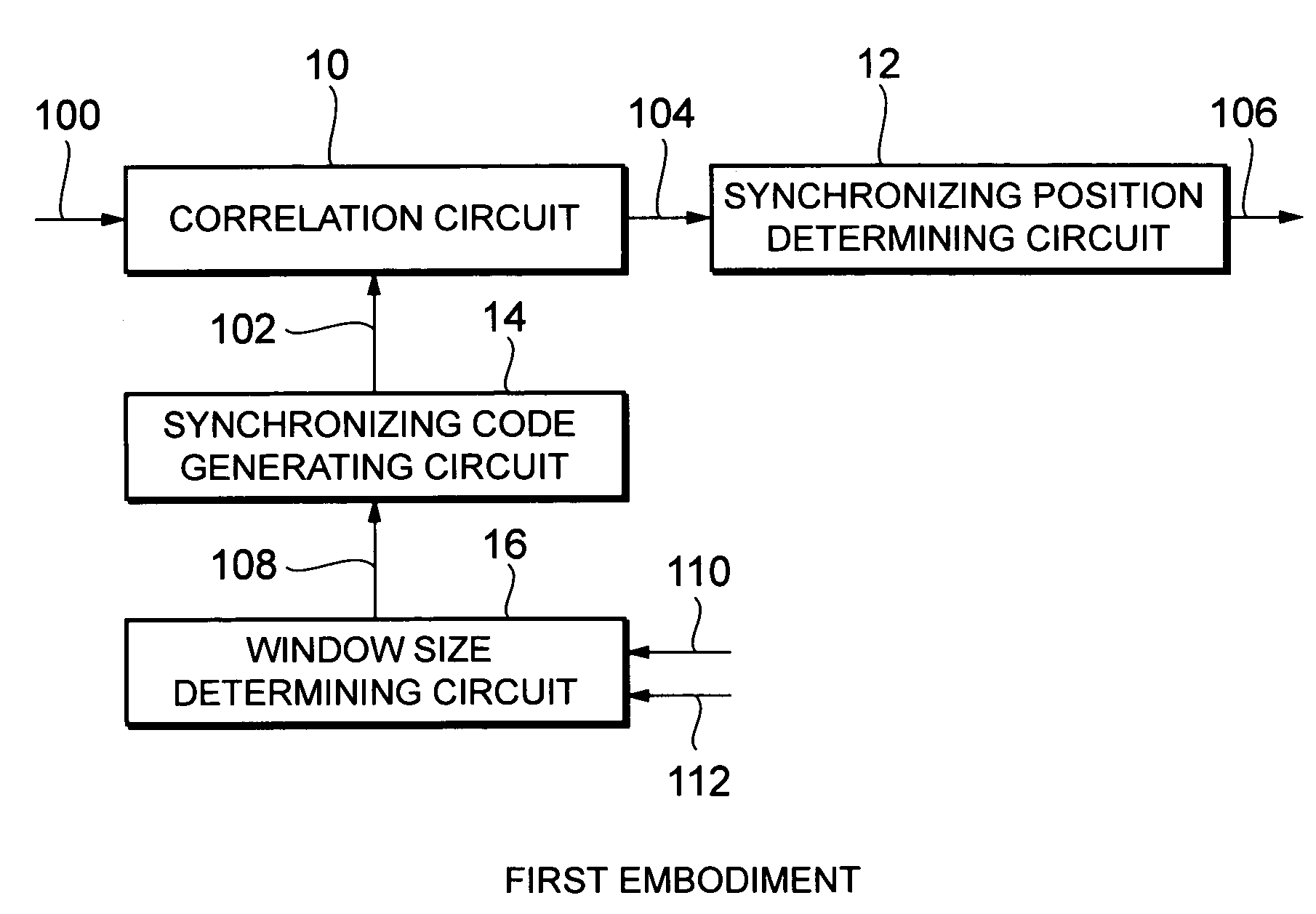
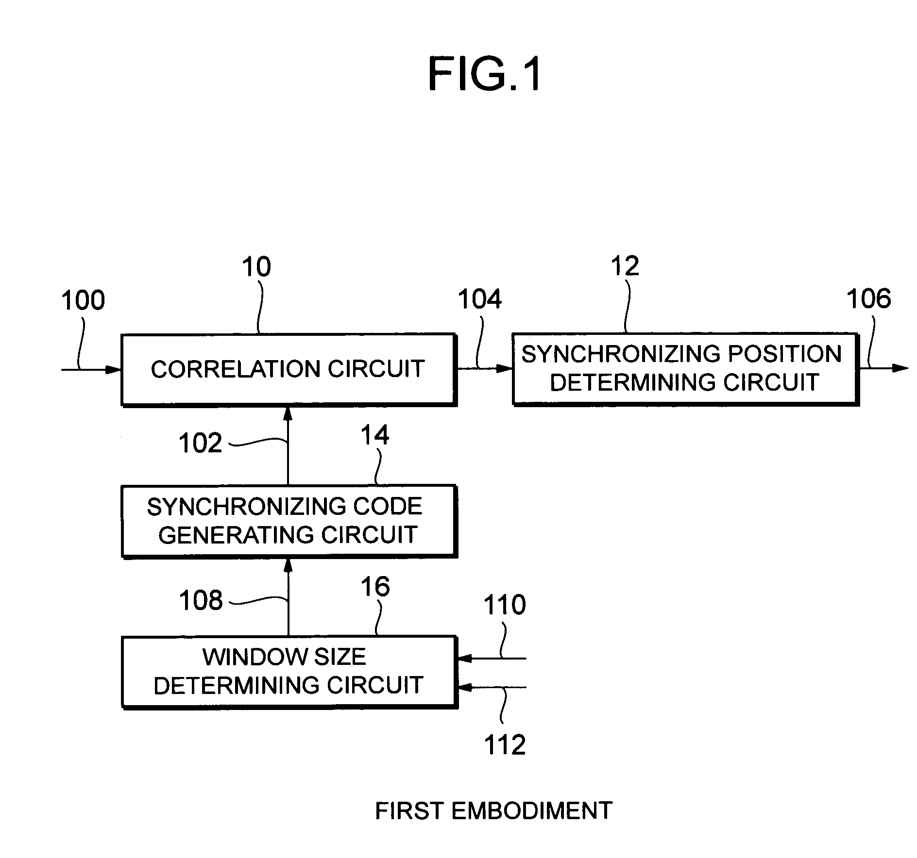
[0012]Now, preferred embodiments of synchronizing position detecting circuits according to the present invention will be described in detail with reference to the accompanying drawings. FIG. 1 is a structural diagram showing the synchronizing position detecting circuit according to the present invention. This synchronizing position detecting circuit is used, for example, in a receiving device, which performs intermittent reception, of a mobile station in a CDMA mobile communication system, and is particularly suitable for employment in a receiving device of a mobile station that moves on a straight line connecting between a base station and the mobile station or on a prolongation of that straight line.

[0013]As shown in FIG. 1, the synchronizing position detecting circuit of this embodiment comprises a correlation circuit 10, a synchronizing position determining circuit 12, a synchronizing code generating circuit 14 and a window size determining circuit 16. The synchronizing position...

second embodiment

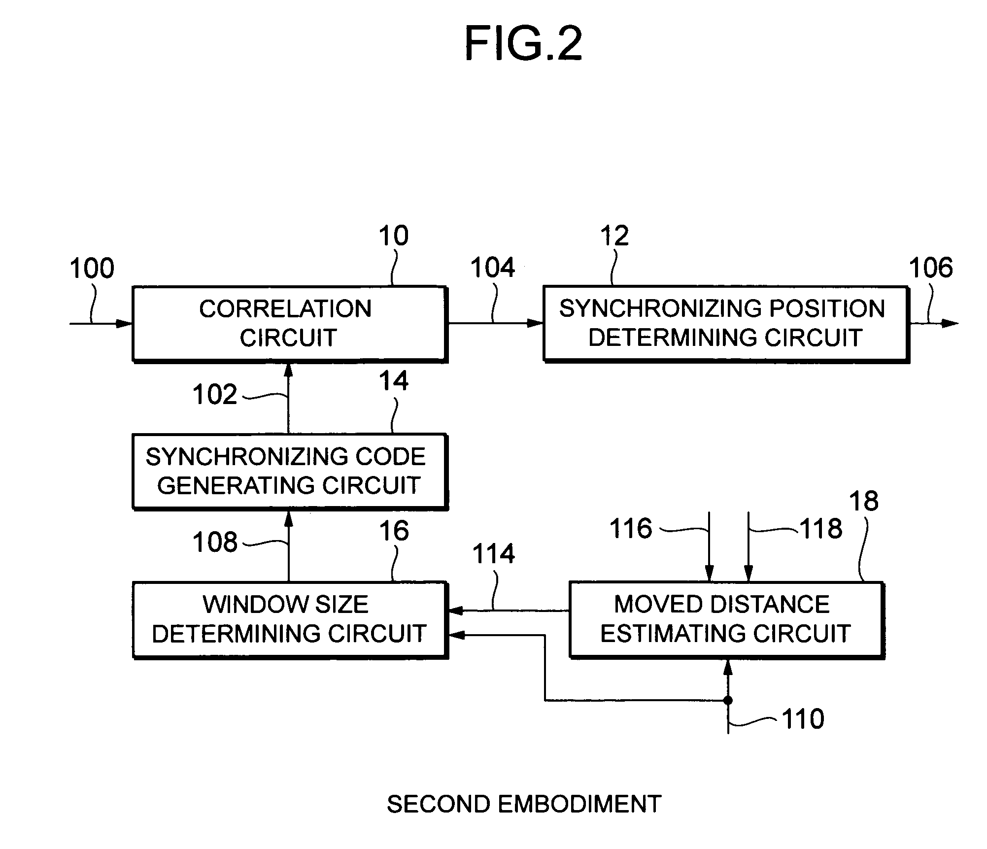
[0030]As described above, a change in straight line distance (estimated moved distance) between the base station and the mobile station caused by movement of the mobile station during the sleep time is calculated using the position information representing the moved position of the mobile station, and the size of the window for searching for the received signal 100 is determined based on the estimated moved distance. Therefore, it is possible to capture the received signal 100 securely and quickly without losing it. Further, there is also an advantage in that the window size can be determined without taking into account the moving direction and speed of the mobile station.

[0031]As described above, according to the synchronizing position detecting circuit of the present invention, when the mobile station moves on a straight line connecting the base station, the size of the window for searching for the received signal is determined taking into account the moved distance of the motile...


PUM


Abstract

A synchronizing position detecting circuit includes a window size determining circuit, a synchronizing code generating circuit, a correlation circuit and a synchronizing position determining circuit. The window size determining circuit calculates a moved distance of a mobile station during a sleep time based on a moving speed and the sleep time and selects a window size based on a phase change of a distance signal corresponding to the moved distance. The code generating circuit repeatedly produces a synchronizing code that coincides with a part of a code of the distance signal and successively shifts a phase of the synchronizing code by a predetermined phase width so as to shift the window size. The correlation circuit calculates a correlation function between the synchronizing code and the distance signal. The position determining circuit determines a correlation function having a maximum value to detect the distance signal and outputs a synchronizing position signal representing a detecting position.

Description

BACKGROUND OF THE INVENTION[0001]The present invention relates to a synchronizing position detecting circuit that detects a received signal repeating a prescribed code to output a synchronizing position of the received signal and, in particular, relates to a synchronizing position detecting circuit suitable for a CDMA (Code Division Multiple Access) mobile station receiving device that carries out intermittent reception.[0002]In the CDMA mobile communication system, for example, a base station multiplies an information signal by a spreading code and transmits it to a mobile station, while the mobile station demodulates the information signal by producing a spreading code having the same pattern and phase as those of the spreading code of the base station and multiplying the signal received from the base station by the produced spreading code (despreading), so that it is necessary for the mobile station to acquire phase information of the spreading code of the base station. On the ot...

Claims


Application Information

Patent Timeline
IPC IPC(8): H04B1/69G01S3/02H04B1/707H04B1/7075H04B7/26H04L7/08H04W52/02H04W56/00H04W76/02
CPCH04B1/70754H04B2201/70715
Inventor AKITA, HIDENORI
Owner LAPIS SEMICON CO LTD
Learn More