
Multipurpose motor vehicle with two coaxial parallel wheels and more electromagnetic holonomic wheels in tandem

a multi-purpose, parallel-wheel technology, applied in the direction of bicycles, transportation and packaging, unicycles, etc., can solve the problems of limiting the number of motors used to drive each wheel, reducing the design stability of the design, and heavy wheels, so as to increase the diameter of wheels and lend stability to the design

Inactive Publication Date: 2007-10-23
PAL ANADISH KUMAR
View PDF4 Cites 3 Cited by
  • Summary
  • Abstract
  • Description
  • Claims
  • Application Information

AI Technical Summary

Benefits of technology

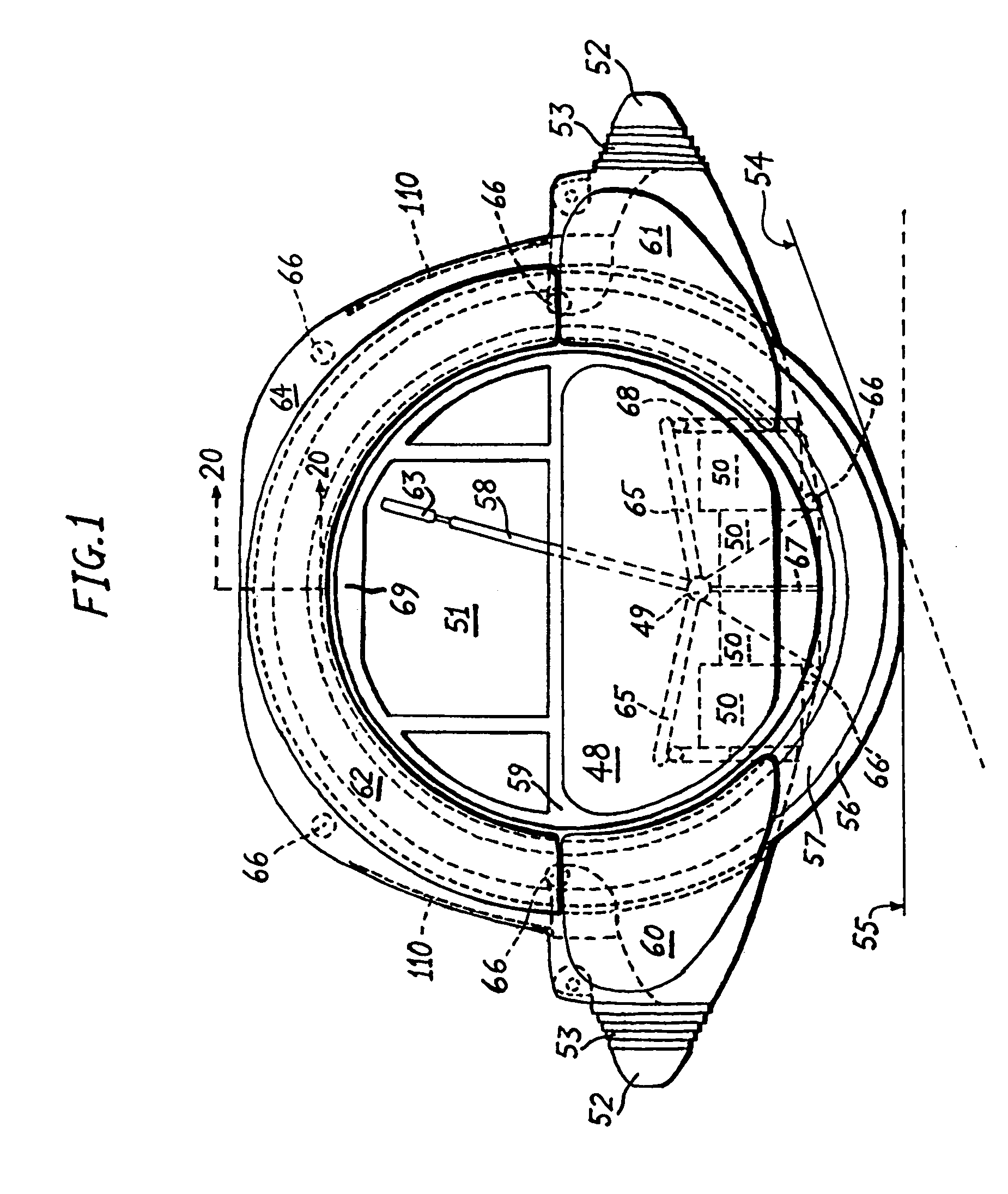
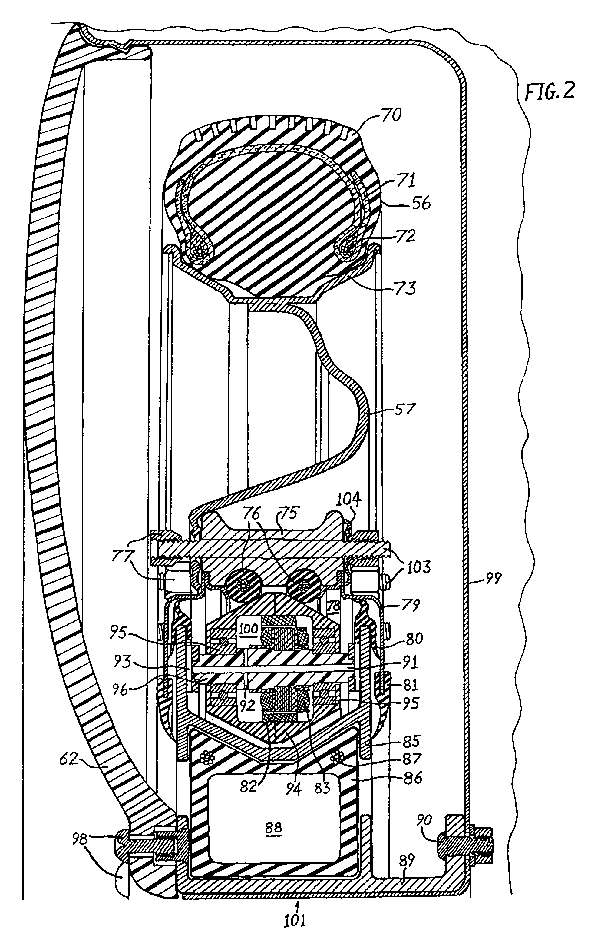
[0009]This invention solves the earlier problems by first increasing the diameter of wheels. In the first version, the wheels, two in number, get integrated with the shell of the vehicle, dispensing with the solid axle of existing electrical vehicles. The shell of this electric motor vehicle is basically in the form of a modified cylinder with crush zones added on the front and the rear of the vehicle, a portion of the cylindrical side of which faces the surface on which the vehicle travels; both ends of the modified cylinder remain vertical, and these two ends also act as openings with partial or full doors. The two wheels in annular form are mounted on the two ends, with the use of toroidal pneumatic flexible mounts. These mounts allow axle formations to deflect in sympathy with radial deflections happening due to impacting forces acting on the tires; and the flexible mounts absorb the deflections, preventing them from distorting the wheels or the axle formations. The modified cylindrical shell of the vehicle thus acts as the axle formation for both the wheels. The electrical energy storage devices are kept near that surface of the shell the other side of which always faces the ground; the positioning of the electrical energy storage devices makes the center of gravity of the vehicle low and lends stability to the design—this is possible, because all the electrical energy accumulators and superconductor assemblies are heavy. Numerous lightweight brush-less dc motors housed in biconic rotors circumferentially locate rotatably the inner annular surface of both the wheels. Both the wheels are driven by individual switching regulators powering the BLDC motors, also effecting regenerative braking when needed. Steering is accomplished by differential rotation of the respective wheels.
[0011]The second version of the present invention forms a traction vehicular arrangement. In this form, by adjusting the height of the passenger seat to a low it can be turned into a vehicle similar to the version described hereinabove. Otherwise, the traction vehicular arrangement functions in conjunction with wheeled trailers. It is equipped with a hook on the front and the rear. The passenger seat can be rotated vertically to make the occupant of the seat sit facing the opposite side. This effectively makes this vehicle with an interchangeable front and rear. Both ends of the modified cylinder in this version of the present invention are not used as doors; rather, they are blocked by the annular laminar extension of the hub of the wheels nearly reaching the central axis. This way the entry of foreign material can be blocked completely from entering the bearing and driving mechanisms of the wheels.
[0013]Accordingly, a principle object of the present invention is to simplify the construction of small electric motor vehicle.
[0016]Another object of the invention is to develop a large-diameter holonomic wheel with powered rollers forming the tire to have active control while steering and to avoid bending forces on the wheel axle generated by the travel of the vehicle on which the holonomic wheel is fixed.
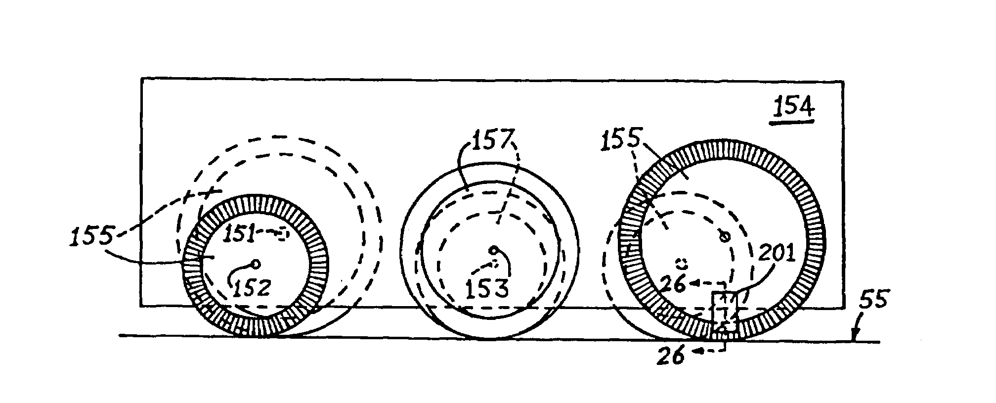
[0017]An additional object of the invention is to devise a large vehicle augmenting the reliability of the concept of two parallel wheels put side by side, forming a vehicle with an addition of holonomic wheels with powered rollers forming the tire.

Problems solved by technology

But as there are no gears in the case of a direct-driven wheel motor, in order to generate a high torque, either the diameter or the thickness of the wheel motor has to be increased: This makes the wheel motor heavy.
The rigid coaxial nature of the two parallel wheels in those vehicles restricts the use of the vehicles to low traveling speeds.
Further, the electrical drive motors for the two wheels are located outside the wheel hubs, which limits the number of motors used to drive each wheel without sacrificing useful windscreen width of the vehicles.
The bearings of the annular wheels have no provisions to protect against foreign materials from getting into their engaging surfaces.
The use of very large wheels does not eliminate other driving mechanisms outside the wheels, excepting a separate steering mechanism.
These impacts bring about point distortions in the wheel, increasing the friction in the rotation of the wheels.
Except in U.S. Pat. No. 6,547,340, rest of the designs fail to compensate for the uneven wear in the rollers in case of rectilinear motion by the vehicle having such wheels.
However, in U.S. Pat. No. 6,547,340, there is no control over the necessary rotation of each roller after it leaves ground contact as the holonomic wheel rotates and the vehicle travels.
However, not before they have exerted bending stresses on each of the axles of the holonomic wheels.
Nonuniform ground friction has to be compensated for by varying wheel rotation in response, as there is no direct control over the rollers on the holonomic wheels of existing art.

Method used


Image

  • Multipurpose motor vehicle with two coaxial parallel wheels and more electromagnetic holonomic wheels in tandem
  • Multipurpose motor vehicle with two coaxial parallel wheels and more electromagnetic holonomic wheels in tandem
  • Multipurpose motor vehicle with two coaxial parallel wheels and more electromagnetic holonomic wheels in tandem

Examples


Embodiment Construction

[0035]The first version of the present invention is described in detail with the aid of FIG. 1 through FIG. 4. The total height of the vehicle in FIG. 1 is nearly 1370 mm. In this present form, it is designed to accommodate two persons with some luggage space at the back. The seats are marked 65 in FIG. 1, FIG. 3 and FIG. 4. Batteries 50 in FIG. 1 are placed below seats 65. There is a provision to keep eight 100AH 12V lead acid batteries. The total weight of the batteries is approximately 240 kg. The position of batteries 50 keep the center of gravity of the vehicle very low; this, coupled with the eccentric loading on the vehicle, provides stability to the vehicle, in spite of its having only two parallel wheels. The top and front sides of the battery enclosure have to be strong and fully linked with the structure of the shell and, at the extremities, with the direct-drive rim motors: So that, in case of an accidental collision, the batteries 50 do not damage the legs of the occupa...


PUM


Abstract

A vehicle with zero turning radius employing a minimum of two generally parallel matching annular wheels mounted with independent pneumatic toroidal suspensions fixed coaxially on a chassis. The wheels have mounted on their inner hub sides frictional linings along which run a respectively equal number of circumferentially distributed truncated-bicone-shaped rotors of brush-less dc motors with stator shafts fixed on to the axles of the wheels. Addition of a number of large holonomic wheels in tandem on either side of the two generally parallel wheels makes the vehicle longer and more stable. The large holonomic wheels have tires formed by a toroidal unanimity of disc-like rollers with magnetic or electromagnetic elements radially distributed evenly to make each disc-like roller rotate or resist rotation perpendicular to the holonomic wheel axis by acting as a rotor to motor stator windings attached to the chassis in proximity with the ground-engaging portion of the tire.

Description

CROSS-REFERENCE TO RELATED APPLICATIONS[0001]Present application is a continuation in part of U.S. patent application Ser. No. 09 / 781,090 filed on Jan. 12, 2001, now U.S. Pat. No. 7,017,696. The matter disclosed in the present application formed the amendment to application Ser. No. 09 / 781,090, received by the United States Patent and Trademark Office on Sep. 1, 2004.STATEMENT REGARDING FEDERALLY SPONSORED RESEARCH OR DEVELOPMENT[0002]Not ApplicableREFERENCE TO A MICROFICHE APPENDIX[0003]Not ApplicableBACKGROUND OF THE INVENTION[0004]The present invention is directed to the field of electrical motor vehicles with zero turning radius. It also relates to those vehicular designs in which steering of the vehicle is not done by moving the axles of the wheels.[0005]There had been designs in the past, which utilized an electric motor inside the wheel. On many occasions the wheel is turned into a wheel motor (U.S. Pat. No. 5,894,902). But as there are no gears in the case of a direct-driven...

Claims


Application Information

Patent Timeline
Patent Type & Authority Patents(United States)
IPC IPC(8): B60K1/02B60K7/00B62D61/00B62K1/00
CPCB60K7/0007B62K1/00B62D61/00B60K17/046B60K2007/0092B60K2007/0046
Inventor PAL, ANADISH KUMAR
Owner PAL ANADISH KUMAR
Learn More