
Implantable lead system with seed electrodes

a seed electrode and implantable technology, applied in the field of implantable medical leads, can solve the problems of inability to precisely localize with scalp electrodes, affecting the signal-to-noise ratio, and occupying a small space, so as to reduce the excess of slack, reduce the risk of fracture and erosion, and reduce the effect of excess slack

Active Publication Date: 2007-10-16
NEUROPACE
View PDF8 Cites 19 Cited by
  • Summary
  • Abstract
  • Description
  • Claims
  • Application Information

AI Technical Summary

Benefits of technology

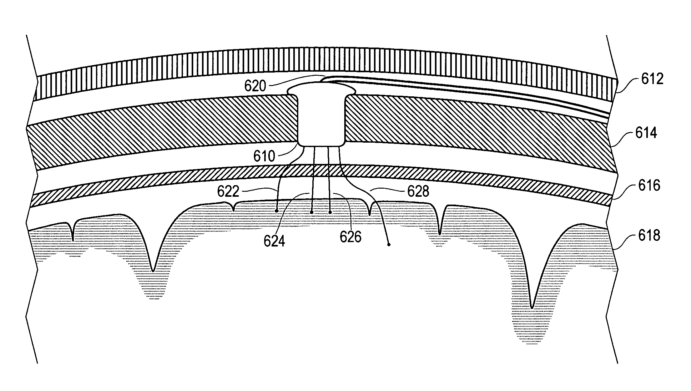
[0011]A medical electrical lead system in accordance with the present invention addresses the shortcomings of existing implantable lead systems by providing multiple independently positionable “seed electrodes”. A seed electrode system according to the invention has independent leads that have minimal excess slack, and thus are resistant to breakage and erosion, and take up little space. The seed electrodes are small and have minimal mass, thereby avoiding inertial movement, and resisting changes due to brain atrophy. Seed electrodes according to the invention are relatively easy to implant, stay in place, and are believed to be less traumatic than traditional depth leads (thereby enabling new surgical strategies, including implanting many seed electrodes and interfacing relatively few of them to a device).
[0013]An introducer apparatus is specially configured to implant the seed electrodes of the present invention. The introducer apparatus is adapted to interface with one or more commonly used Stereotactic head frame assemblies and to accurately position the seed electrodes of the invention within the patient's brain. In an embodiment of the invention, the introducer apparatus includes a relatively rigid insertion cannula, a push tube, and a depth calibrating spacer. The seed electrode is releasably attached to the insertion cannula such that the push tube can be manipulated to break the attachment and leave the seed electrode in place while the cannula is retracted.
[0014]With a lead system in accordance with the present invention, it is possible to realize several additional advantages. With plural individually positionable distal electrodes, it is possible to reach a larger number of separate brain sites while limiting the number of leads necessary to do so. The number of leads connected to an external apparatus or implanted neurostimulator (or other device) is minimized, thereby improving the ease of treating the patient, improving ease of lead management, reducing the possibility of lead breakage, and reducing the possibility of discomfort or erosion under the patient's scalp.

Problems solved by technology

Although it is frequently possible to employ scalp electrodes for certain types of EEG monitoring and analysis, it has been found that ambient electrical noise (such as from the 50 / 60 Hz power system) can adversely impact signal-to-noise ratio, and certain signal components of interest may be filtered out by the patient's intervening cranium and scalp tissue.
Moreover, precise localization is less feasible with scalp electrodes.
Unfortunately, brain surface strip and grid electrode arrays have a tendency, particularly with long-term chronic use, to move away from the surface of the brain.
The result is frequently unsatisfactory or intermittent electrical contact between the electrodes and the desired brain tissue.
It frequently requires further surgery (with the associated risks for the patient) or electronic compensation for the change in characteristics (with a potentially harmful increase in stimulation current being delivered to the brain, or at minimum, decreased signal-to-noise ratio), and may result in long-term performance deterioration.
There is no known acceptable way to anchor a traditional strip or grid electrode array to the surface of the brain.
Moreover, the electrodes are spaced evenly along a line or grid, and while it is possible to orient a strip or grid electrode array in a desired manner, it is generally not possible to position the individual electrodes independently.
It is difficult, and usually impractical, to attempt to position the individual electrodes independently.

Method used


Image

  • Implantable lead system with seed electrodes
  • Implantable lead system with seed electrodes
  • Implantable lead system with seed electrodes

Examples


Embodiment Construction

[0025]The invention is described below, with reference to detailed illustrative embodiments. It will be apparent that a system according to the invention may be embodied in a wide variety of forms. Consequently, the specific structural and functional details disclosed herein are representative and do not limit the scope of the invention.

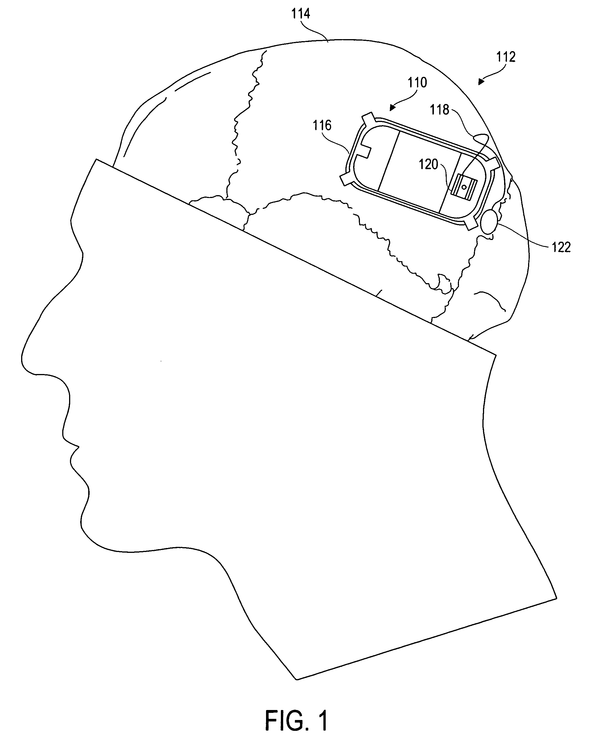
[0026]An implantable neurostimulator device 110 according to the invention, as implanted intracranially in a patient 112, is illustrated in FIG. 1. The device 110 is affixed in the patient's cranium 114 by way of a ferrule 116. The ferrule 116 is a structural member adapted to fit into a cranial opening, attach to the cranium 114, and retain the device 110.

[0027]To implant the device 110, a craniotomy is performed in the parietal bone anterior to the lambdoidal suture to define an opening slightly larger than the device 110. The ferrule 116 is inserted into the opening and affixed to the cranium 114, ensuring a tight and secure fit. The device 110 is...


PUM


Abstract

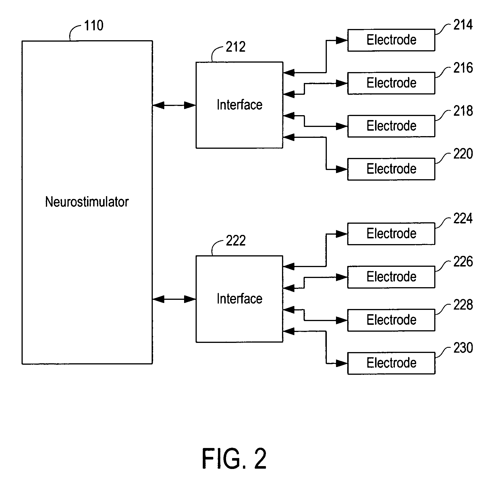
A medical electrical lead system for neurological applications has a distal portion having a plurality of independently positionable seed electrodes, each of which may be connected via an interface to an implantable medical device. The interface allows the seed electrodes to be positioned, then excess wire trimmed, facilitating simplified connection of multiple independent electrodes to a single device. Seed electrodes according to the invention are small, have relatively low mass, and are minimally destructive of surrounding tissue.

Description

FIELD OF THE INVENTION[0001]The invention is related to implantable medical leads, and more particularly to implantable electrical leads used to sense electrographic signals from a patient's brain or to apply electrical stimulation to the brain.BACKGROUND OF THE INVENTION[0002]In the medical diagnosis and treatment of various brain disorders, including epilepsy, Parkinson's disease, sleep disorders, and psychiatric ailments, it is customary and frequently useful to analyze electrical signals originating in the brain. For a review of this technology, see Ajmone-Marsan, C., Electrocorticography: Historical Comments on its Development and the Evolution of its Practical Applications, Electroencephalogr. Clin. Neurophysiol. Suppl. 1998, 48:10-16; there are numerous other applications. These electrographic signals are commonly known as electroencephalogram (EEG) signals when originating or received at the surface of the brain, such as from scalp electrodes, or electrocorticogram (ECoG) si...

Claims


Application Information

Patent Timeline
Patent Type & Authority Patents(United States)
IPC IPC(8): A61B5/04A61N1/05A61B5/0478
CPCA61B5/0478A61N1/0539A61N1/0529A61B5/291
Inventor BOLING, C. LANCE
Owner NEUROPACE
Learn More