
Digital camera and function appending method for the same

a function appending and digital camera technology, applied in the field of digital cameras, can solve the problems of image quality easily deterioration, image lack of stability, and a lot of time, and achieve the effect of reducing the overhead time into substantial zero and simplifying the operation of print processing

Inactive Publication Date: 2007-10-16
SEIKO EPSON CORP
View PDF18 Cites 11 Cited by
  • Summary
  • Abstract
  • Description
  • Claims
  • Application Information

AI Technical Summary

Benefits of technology

[0015]When the requests such that simplification of the operation in the print processing of the resultant picked-up image and reduction of the overhead time into substantial zero are checked in the digital camera, it is preferable that, for example, the image data are directly output from the digital camera to the printer without the intervention of the PC and thus the picked-up image can be printed. Especially, since the user without the PC can also get simply the resultant picked- up image by the digital camera, satisfaction of such requests will be expected to contribute to the wide spread of the digital camera.

Problems solved by technology

However, since the D / A conversion in the digital camera and the A / D conversion on the video printer side are repeated, there are such problems peculiar to the analogue technology that the quality of image is easily deteriorated and also the image lacks the stability.
However, there are such problems that it take a lot of time (so-called an overhead time) to load the command input, the print processing application program, and the printer driver and that it requires time to start up the PC because several minutes are needed at least.
In addition, although the spread of the PC is remarkable, many problems to be solved further are still remain in handling the PC actually.
There is an indication that a large majority of the PC owner merely have the PC but they cannot handle the PC.
In order to print the resultant image picked up by the digital camera, there are also such problems that there will be caused disadvantages that it is hard to install them or it is not understood how to input the command even if these users buy the image (video) print processing application program and the printer driver and then try to install them into the PC.
Furthermore, there are also such problems that to prepare the expensive PC for merely printing the picked-up image spoils extremely the user's convenience.

Method used


Image

  • Digital camera and function appending method for the same
  • Digital camera and function appending method for the same
  • Digital camera and function appending method for the same

Examples


embodiments

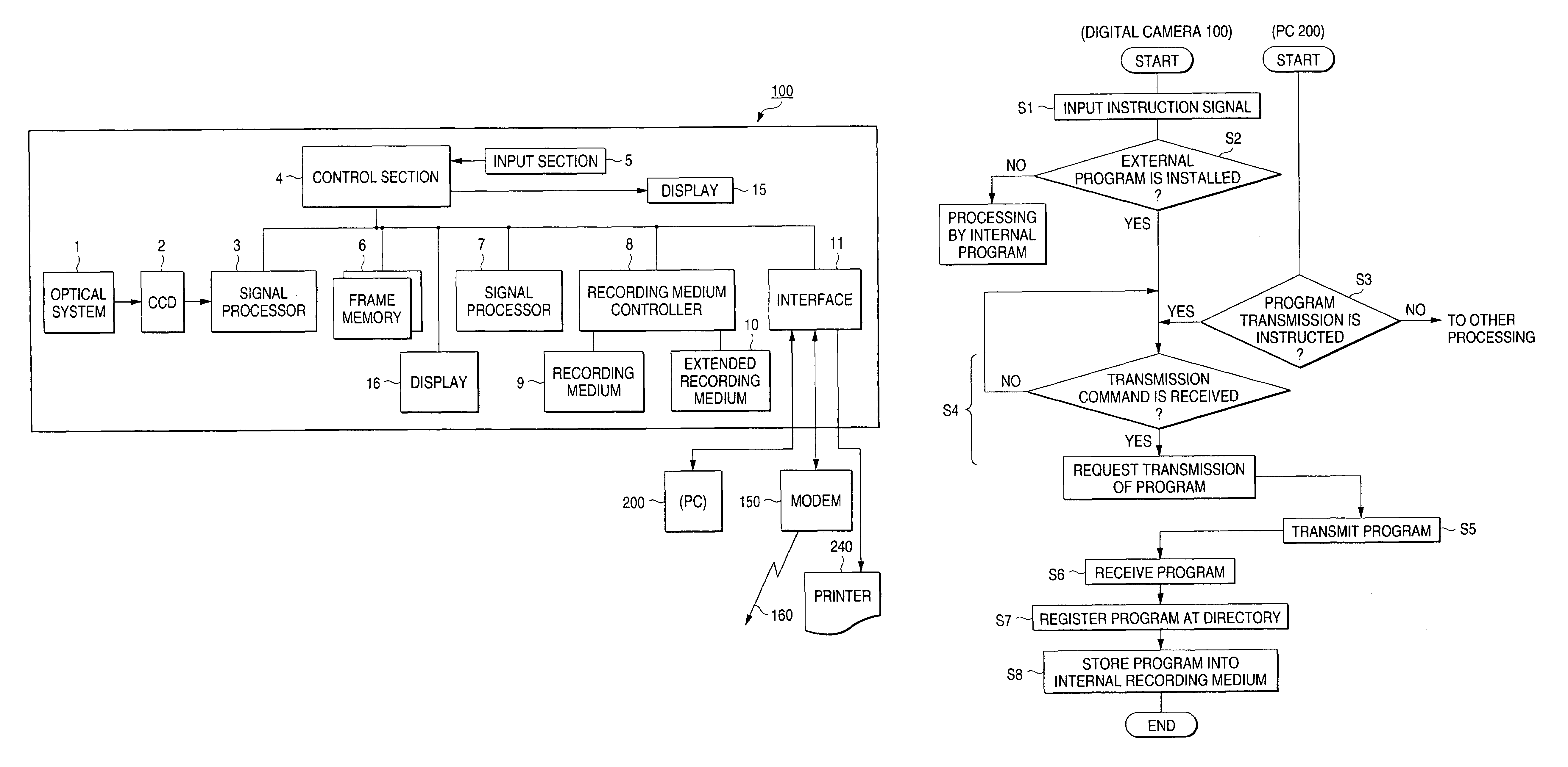
[0075]FIG. 4 is a view showing an example of print image data generating programs which are installed into the digital camera from the external device. The installed print image data generating programs 50 comprises a data expansion program 51, an RGB conversion program 52, a printer driver 53, and a print data transmission program 54. Also, the printer driver 53 includes a rasterizer 531, a color correction module 532, and a halftone module 533, which have the same configurations as the printer driver for the print image data generating processing by the personal computer, etc.

first embodiment

[0076](1) Installing of External Program

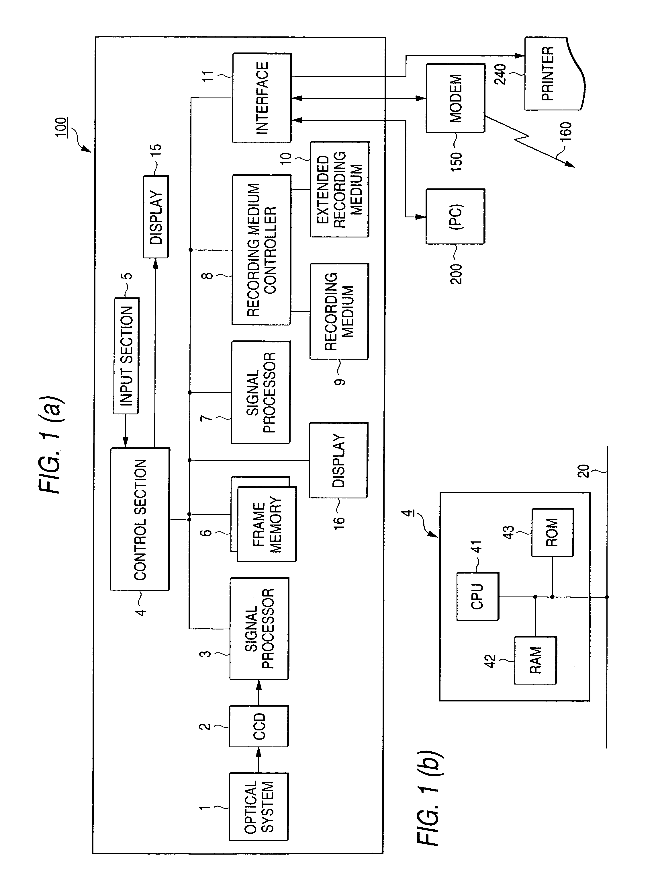
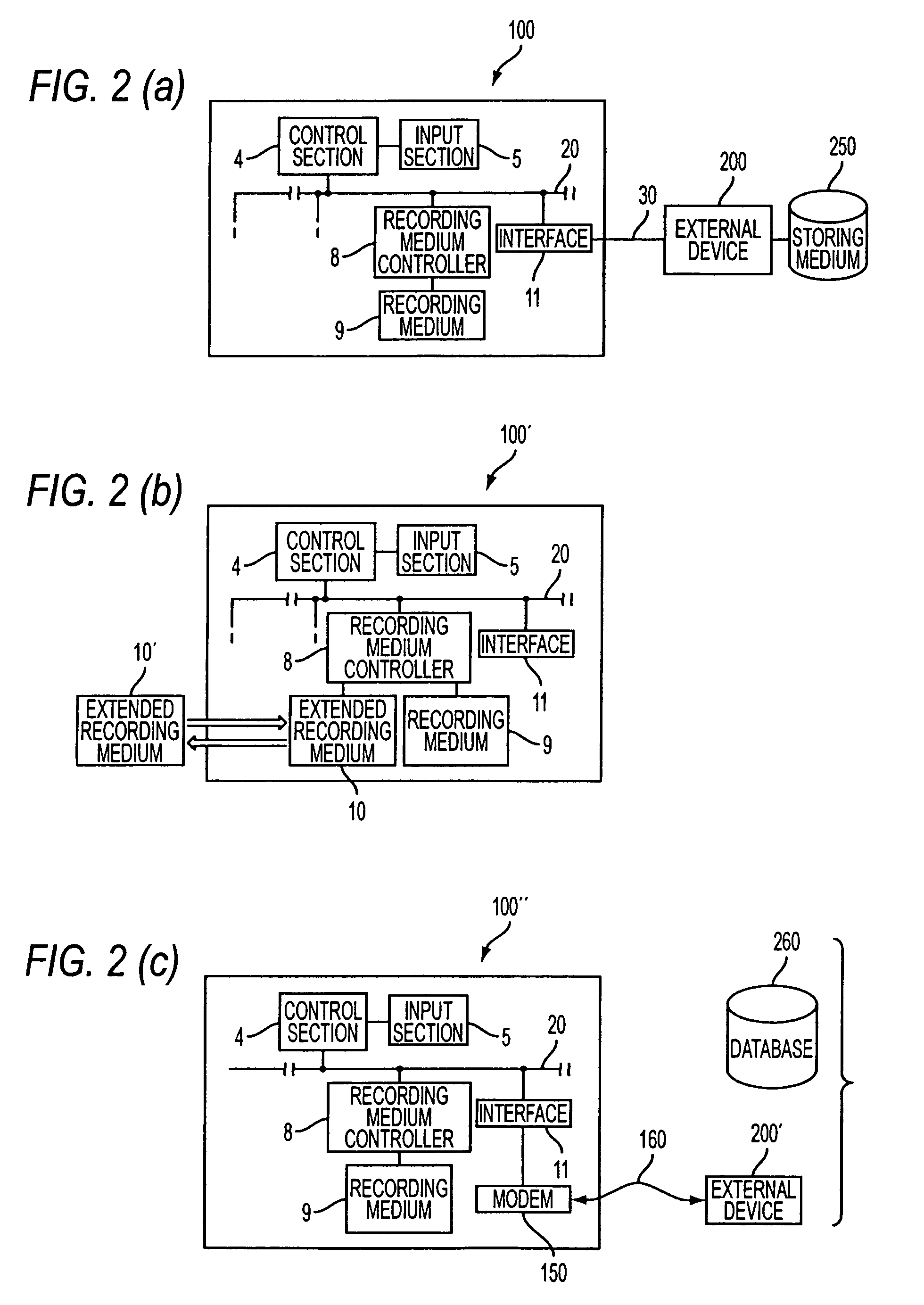
[0077]FIG. 5 is a flowchart applied when the print image data generating program should be installed from the external personal computer system such as the PC, etc. into the digital camera 100. The installing of the print image data generating program will be explained with reference to FIG. 1, FIG. 2(a), FIG. 3, and FIG. 4 hereinafter.

[0078]As premises, it is assumed that a power supply of the digital camera 100 is turned ON, the user turns ON a program installing switch provided on the digital camera 100, the PC 200 and the digital camera 100 are connected to each other via a dedicated cable 30, and the user executes the operation to transmit the program from the program storing medium 250 (e.g., magnetic disk) of the PC 200 to the digital camera 100.

[0079]When the program installing switch is turned ON, the input section 5 sends a switch-ON signal to the control section 4 (S1). The program installing switch is used commonly with an image di...

second embodiment

[0108]FIG. 8 is a flowchart applied when the print image data generating program is installed from the externally extended recording medium such as the memory card, etc. to the digital camera 100. In this case, deletion of the installed and recorded print image data generating program and also the direct print processing onto the ink jet printer device by the installed print image data generating program are similar to those in the first embodiment (FIG. 6, FIG. 7). The second embodiment will be explained with reference to FIG. 1, FIG. 2(b), FIG. 3, and FIG. 4 hereinafter.

[0109]As premises, it is assumed that the power supply of the digital camera 100 is turned ON, the extended recording medium such as the memory card in which the print image data generating program is stored is set into the digital camera 100 by the user, and the user turns ON the program installing switch.

[0110]In FIG. 8, when the program installing switch is turned ON, the input section 5 sends the signal equival...


PUM


Abstract

There is provided a digital camera to which external programs can be installed for appending desired functions thereto. Print image data generating programs to be stored in a recording medium in the digital camera are transmitted from a personal computer, an external extended recording medium of the digital camera, or an external device via a modem and a communication line. In any cases, the stored programs are read out at desired time to execute an print image data generating processing which transmits the print image data to a printer for printing the image. The stored program can be deleted at a desired time.

Description

CROSS-REFERENCE TO RELATED APPLICATION[0001]This is a continuation-in-part application of PCT / JP98 / 01251 filed on Mar. 20, 1998.BACKGROUND OF THE INVENTION[0002]The present invention relates to a digital camera and, more particularly, a digital camera to which new functions can be attached and a function appending method of appending new functions to the digital camera. As such new functions, there are a direct print function for printing picked-up image data with the use of a printer, a communication function for transmitting the image data to terminals located at remote places by using a transmission network, etc.[0003]In recent years, the digital camera (electronic still camera) are developed and on the market, and are now spreading. Normally the picked-up image result by the digital camera (digitized color image data) are printed. A personal computer (abbreviated as “PC” hereinafter) and a printer, a video printer, or the like are employed to output the print.[0004]In the case o...

Claims


Application Information

Patent Timeline
IPC IPC(8): H04N5/225G06F15/16G06F9/445H04B1/38H04N5/76G06F3/12H04N5/765H04N1/21H04N5/781H04N5/91
CPCH04N1/00973H04N1/2112H04N2201/0082H04N2101/00
Inventor SHIOHARA, RYUICHINAKAJIMA, YASUMASA
Owner SEIKO EPSON CORP
Learn More