
Supporting frame with locating function

a technology of locating function and supporting frame, which is applied in the direction of machines/engines, liquid fuel engines, light and heating apparatus, etc., can solve the problems of inconvenient assembly and achieve the effect of convenient assembly

Active Publication Date: 2007-10-16
ASIA VITAL COMPONENTS SHENZHEN CO LTD
View PDF12 Cites 29 Cited by
  • Summary
  • Abstract
  • Description
  • Claims
  • Application Information

AI Technical Summary

Benefits of technology

The solution enables cost-effective, efficient assembly and improved heat dissipation by allowing direct airflow to the CPU, reducing manufacturing costs and enhancing cooling performance.

Problems solved by technology

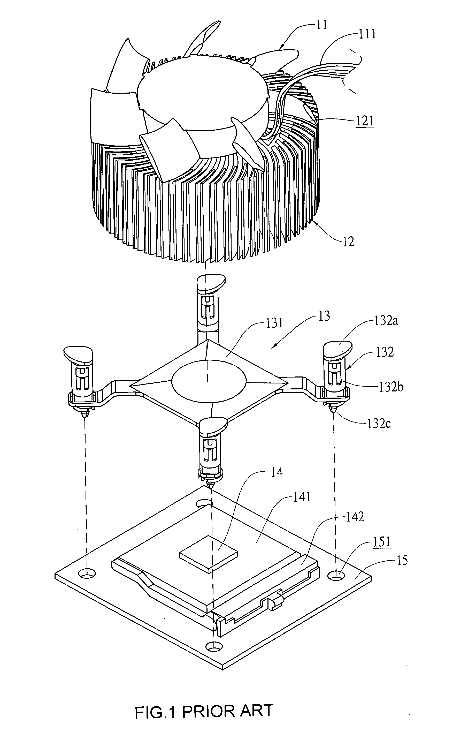
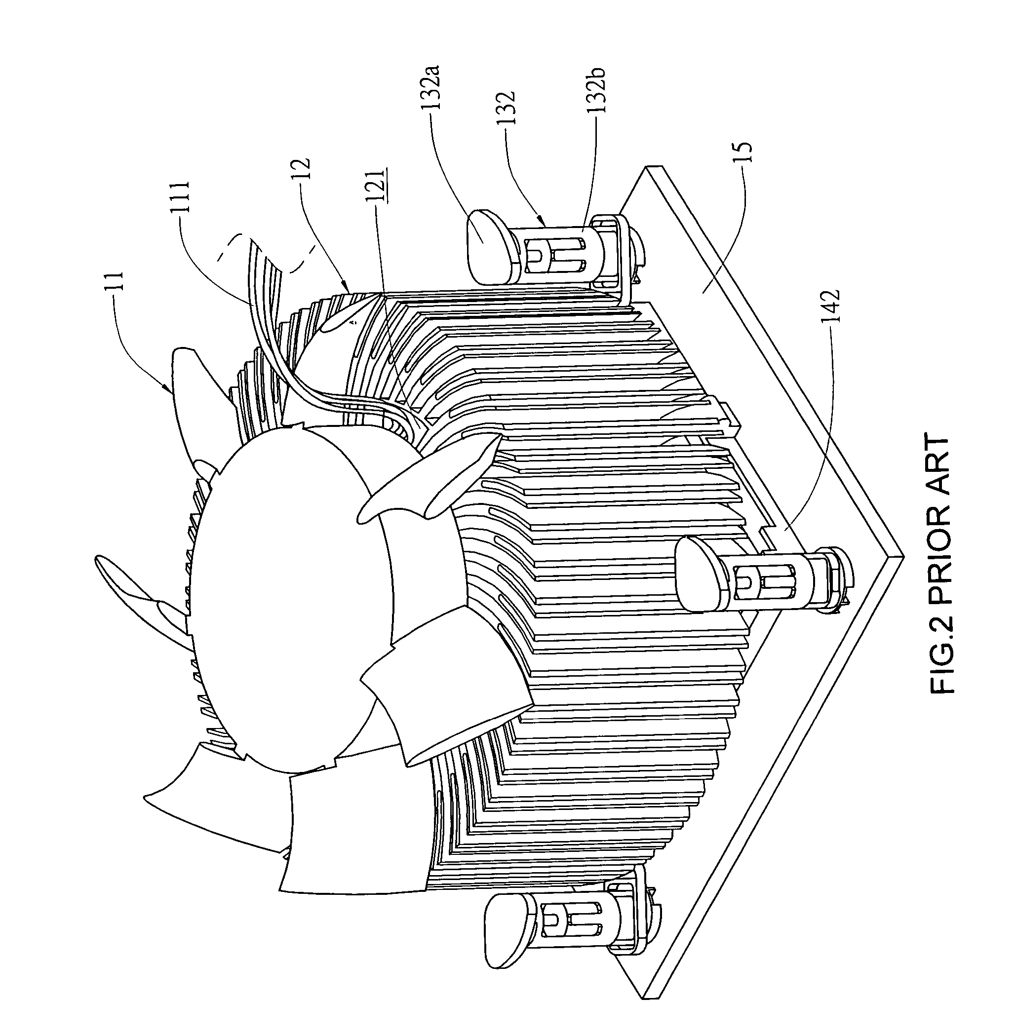
The above-structured supporting frame 13 has the following disadvantages:1. A highly expensive die-cutting cost is required for manufacturing the conventional supporting frame 13.2. To assemble the fan 11 and the radiator 12 to the conventional supporting frame 13, more than one additional step is increased in the process of manufacturing the supporting frame 13 to cause inconvenience in the assembling thereof.3. The fan 11 and the radiator 12 are fixedly assembled to the supporting frame 13, and related parts or components could not be conveniently replaced once the assembling is completed.4. Since the fan 11 is fixed to a top of the radiator 12, it is necessary to provide a recess 121 on the radiator 12 for leading a wire 111 of the fan 11 to an outer side of the radiator 12.5. As can be seen from FIG. 3, the main body 131 of the supporting frame 13 is located below the radiator 12, and airflows produced by the fan 11 and downward sent to the radiator 12 tend to produce a backpressure at the supporting frame 13 to largely reduce the heat radiating effect of the radiator 12.

Method used


Image

  • Supporting frame with locating function
  • Supporting frame with locating function
  • Supporting frame with locating function

Examples


first embodiment

[0027]Please refer to FIGS. 4 and 5 in which a supporting frame with locating function according to a first preferred embodiment of the present invention is shown. As shown, the supporting frame in the first embodiment is generally denoted with a reference numeral 23 and substantially in the form of an annular ring for use over a round-shaped radiator 22. The supporting frame 23 mainly includes a supporting portion 231 and a plurality of connecting portions 232. The supporting portion 231 is provided at a central area with a plurality of hollow spaces 231a, at a rim area with spaced and upward extended locating rods 234 for engaging with receiving holes 211 formed on a fan 21, which is to be located above the supporting frame 23, and also at the rim area with spaced fixing holes 231b, through which fastening elements 231c are extended to thereby connect the supporting portion 231 to a radiator 22 with a lower side of the supporting portion 231 closely bearing against a top of the ra...

second embodiment

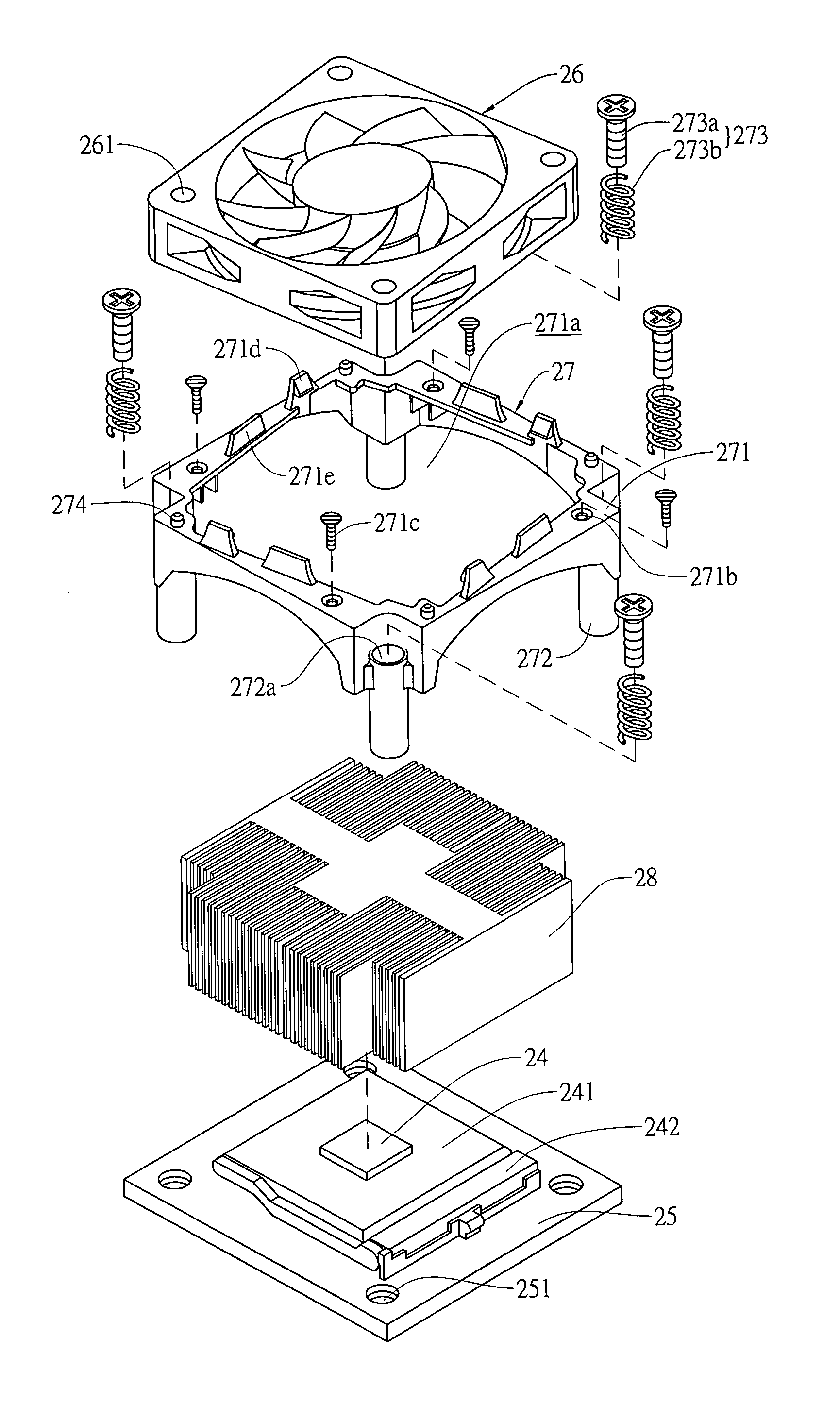
[0030]Please refer to FIGS. 6 and 7 in which a supporting frame with locating function according to a second preferred embodiment of the present invention is shown. As shown, the supporting frame in the second embodiment is generally denoted with a reference numeral 27 and substantially in the form of a polygonal support for use over a polygonal radiator 28. The supporting frame 27 mainly includes a supporting portion 271 and a plurality of connecting portions 272. The supporting portion 271 is provided at a central area with a plurality of hollow spaces 271a, at a rim area with spaced and upward extended locating rods 274 for engaging with receiving holes 261 formed on a fan 26, which is to be located above the supporting frame 27, and also at the rim area with spaced fixing holes 271b, through which fastening elements 271c are extended to thereby connect the supporting portion 271 to a radiator 28 with a lower side of the supporting portion 271 closely bearing against a top of the...


PUM


Abstract

A supporting frame with locating function mainly includes a supporting portion and a plurality of connecting portions. The supporting portion is provided at a central area with a plurality of hollow spaces, and is connected at an upper side to a fan and at a lower side to a radiator. The supporting portion is provided on a rim area with fixing holes, via which fastening elements are extended to connect the supporting portion to the radiator. Each of the connecting portions includes an axially extended connecting hole, in which a locating mechanism is received. The connecting portion is connected at an upper side to the supporting portion, and at a lower side to a main board via screwing and elastic elements of the locating mechanism. With the supporting frame, the fan and the radiator can be quickly assembled to the main board.

Description

[0001]This Non-provisional application claims priority under 35 U.S.C. §119(a) on Patent Application No(s). 093115959 filed in Taiwan, Republic of China on Jun. 3, 2004, the entire contents of which are hereby incorporated by reference.FIELD OF THE INVENTION[0002]The present invention relates to a supporting frame with locating function in connection with a central processing unit (CPU), and more particularly to a supporting frame with locating function for locating a fan and a radiator above a CPU to enable good radiating of heat produced by the CPU during operation thereof.BACKGROUND OF THE INVENTION[0003]FIG. 1 shows a conventional supporting frame 13 mainly including a main body 131 and a plurality of locating mechanisms 132. The main body 131 includes a central area that is in contact with a CPU 14 to transfer heat produced by the CPU 14 during operation thereof to a radiator 12 connected to a top of the main body 131. The main body 131 and the radiator 12 are connected togethe...

Claims


Application Information

Patent Timeline
Patent Type & Authority Patents(United States)
IPC IPC(8): F04D29/60F01D5/08F04D29/58
CPCF04D29/601F04D29/582
Inventor PAN, MING-HUI
Owner ASIA VITAL COMPONENTS SHENZHEN CO LTD
Learn More