
Cooking support frame for food items

a technology for supporting frames and food items, which is applied in the field of accessories for barbeques, can solve the problems of limiting the quantity of food items that can be cooked, food items that are overcooked and others that are undercooked, heat loss and smoke loss

Active Publication Date: 2007-10-16
BARBOUR INT
View PDF12 Cites 55 Cited by
  • Summary
  • Abstract
  • Description
  • Claims
  • Application Information

AI Technical Summary

Problems solved by technology

When grilling poultry wings and legs, several complications arise.
The wings and legs cover a large portion of the grill area relative to the volume of the wings and legs, thus limiting the quantity of food items that can be cooked.
Uneven heat from beneath the grill surface can result in some food items that are overcooked and others that are undercooked, or food items that are both.
With frequent movement of the poultry pieces, heat and smoke are lost whenever the grill lid or oven door are opened.
Heat loss from repeatedly opening the lid or door lengthens the time needed for proper cooking.
Raising the lid also exposes the chef to smoke in the eyes, plus the risk of singed hair and minor burns from flare-ups.
The risk from smoke and flare-ups is greater when applying grilling sauce to the food items.
Also, portions of both wings and legs, e.g. wing tips and the “knuckle” end of legs, can fall between the grill spaces, lodge therein, and become charred.
It is difficult to sufficiently cook the thick portion of meat without overcooking, drying, or burning the thinner portions.
Opening the oven door to turn the poultry results in heat loss, thus lengthening the cooking time.
An increased risk of burns arises due to the cook accidentally touching a hot oven surface while turning the pieces or applying grilling sauce.
The rack system is unsuitable for holding poultry wings and legs in a vertical position.
Indeed, the patent fails to even describe the use of the rack system for cooking poultry legs or wings.
It cannot be used to cook just wings and legs.
The plate inhibits access to the legs in order to apply grilling sauce or to remove pieces that have completed cooking; and it cannot suspend an entire chicken leg below the plate for even cooking of the leg.
Nevertheless, any shrinkage of the food item during cooking can result in the food item dropping from the cradle onto the underlying cooking surface.

Method used


Image

  • Cooking support frame for food items
  • Cooking support frame for food items
  • Cooking support frame for food items

Examples


first embodiment

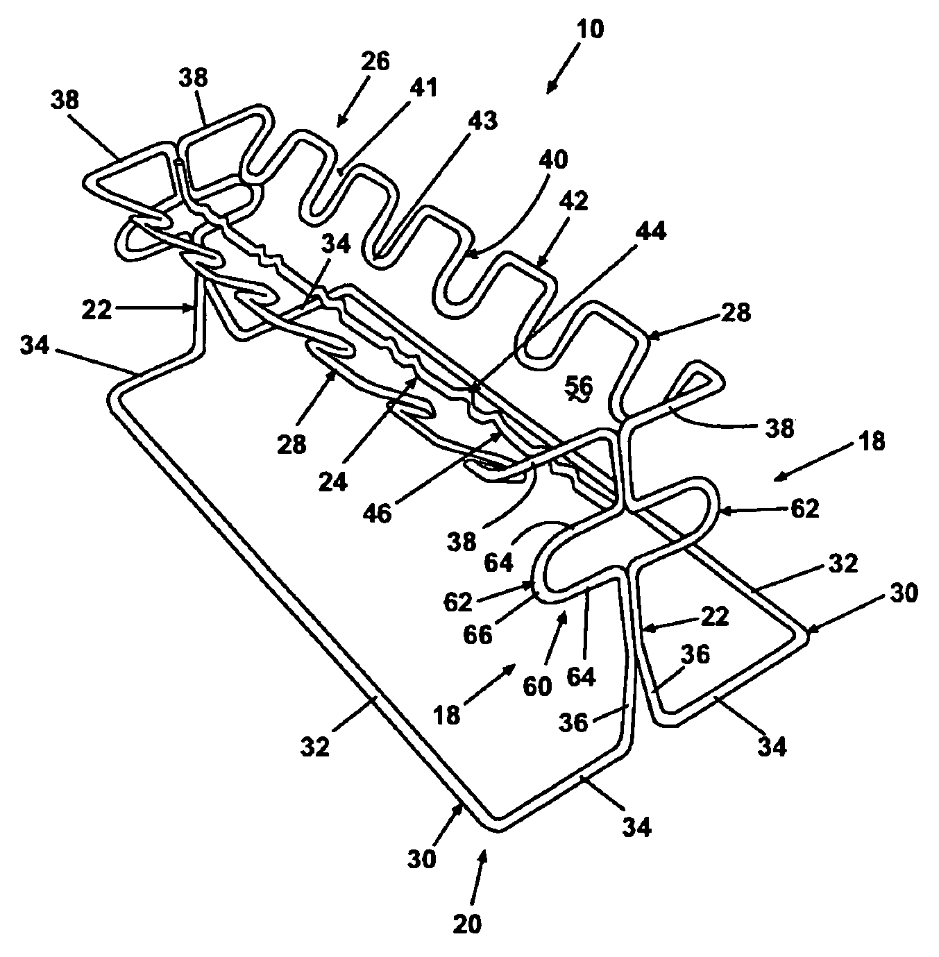
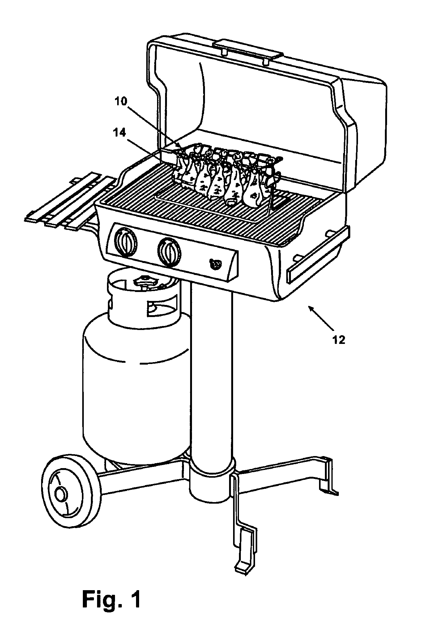
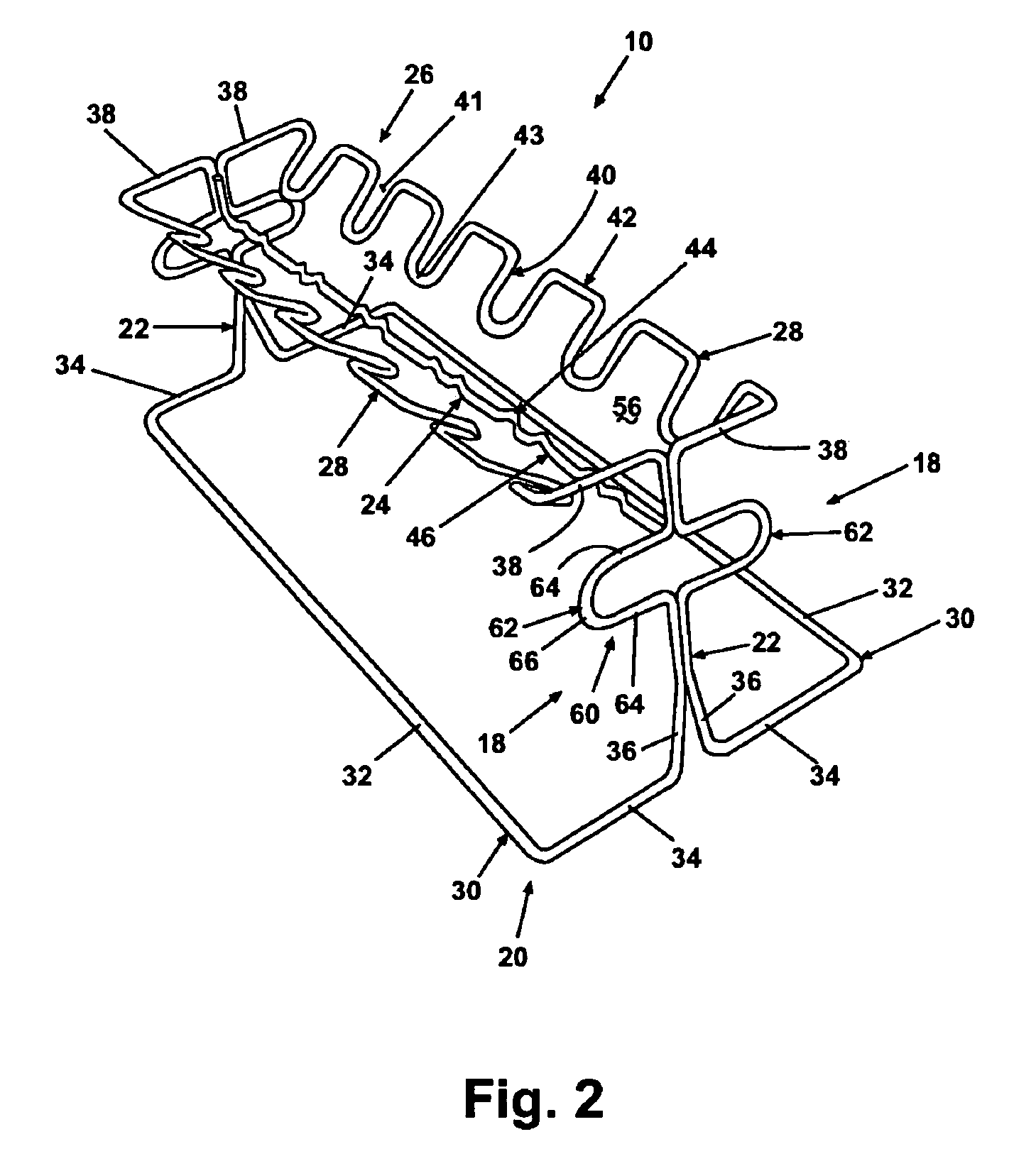
[0044]Referring to the Figures, and in particular to FIGS. 1-6, a cooking support frame 10 according to the invention is illustrated supported on a conventional gas or wood-fired grill 12, and selectively supporting a plurality of poultry legs 14 and poultry wings 18. In a preferred embodiment, the cooking support frame 10 is fabricated of a suitable, heat-resistant wire, such as stainless or nickel-plated steel, which is bent into a complex shape comprising an open base 20, a pair of uprights 22, a center hanger 24, and a hanger assembly 26. Several embodiments of the cooking support frame are described and illustrated herein, all of which are illustrated as fabricated of heat-resistant wire. As well, several embodiments share common elements and, thus, like elements are identified with like numerals. Although the embodiments of the cooking support frame are illustrated and described generally with reference to grilling over a gas or wood-fired grill, the cooking support frame can ...

second embodiment

[0057]Referring now to FIGS. 7, 9, and 10, the cooking support frame 10 is illustrated which is identical to the embodiment illustrated in FIGS. 1-6, except that the longitudinal members 32 transition at an intermediate portion to a pair of rib supports 70, each comprising a pair of parallel, spaced-apart vertical members 74 and a cross member 72 extending therebetween parallel to the longitudinal member 32. Each cross member 72 is parallel to and intermediate the longitudinal member 30 and the lateral hanger 28, so that the rib support 70 can support a variety of food items length-wise along the outer perimeter of the lateral hangers 28, such as a rack of ribs 71, one or more ears of corn, and the like (FIG. 10). Each transverse member 34 is provided with a “crimp” intermediate the longitudinal member 32 and the vertical member 36 to form a rib stop 76 to assist in preventing the lower edge of the rack of ribs 71 from moving laterally along the transverse member 34. The rib support...

third embodiment

[0059]FIG. 8 illustrates the cooking support frame which is identical to the embodiment illustrated in FIGS. 7, 9, and 10, except that the vertical member 74 is formed with an inwardly-extending offset member 78 to support a rack of ribs 71 above the cooking surface along the outside of the rib support 70. This provides for easier placement of the rack of ribs 71 on the frame 10, and, with ribs supported along the inside of the rib support 70 as described above, enables twice the amount of ribs to be cooked.


PUM


Abstract

A cooking support frame comprises a wire rack assembly fabricated from wire subassemblies having slots, crimps, and bends configured for supporting food items such as poultry legs and wings, pork ribs, corn, vegetables, bread, and the like above a conventional cooking surface. An open base supports a pair of opposed uprights having handles formed therein. The uprights support a hanger assembly formed with slots and crimps for holding poultry wings and legs in a generally vertical position. The hanger assembly can comprise an arrangement of removable skewers. The hanger assembly also defines a basket for supporting larger cuts of meat, vegetables, bread, and the like. The open base can be formed with an integral rib rack for supporting pork ribs in a generally vertical position. The cooking support frame is configured for nesting of a plurality of support frames together for shipping, handling, and displaying.

Description

FIELD OF THE INVENTION[0001]The invention relates generally to accessories for barbeque grills, and more particularly to support frames for supporting food items during grilling, baking, and frying.DESCRIPTION OF THE RELATED ART[0002]Outdoor cooking using gas or charcoal-fired grills and smokers is widely done. Popular food items for grilling and smoking include poultry wings and legs, pork ribs, vegetables such as sweet corn, and the like. In the retail grocery market, packs of chicken wings and legs greatly outsell whole or quartered chickens, in part due to the great popularity of buffalo wings and barbequed legs. Grilling turkeys is becoming increasingly popular, as is grilling vegetables. Barbequed pork ribs are a staple of summer fare. Nevertheless, chicken remains a favorite food for grilling. The popularity of grilled foods has also led to oven barbequing, particularly when outdoor cooking is not available.[0003]When grilling poultry wings and legs, several complications ari...

Claims


Application Information

Patent Timeline
IPC IPC(8): A47J43/18
CPCA47J43/18
Inventor BARBOUR, RODNEY A.NEAL, WAYNE A.
Owner BARBOUR INT
Learn More