
Apparatus and methods for detecting and locating signals

a technology for locating signals and apparatus, applied in direction/deviation determining electromagnetic systems, navigation instruments, instruments, etc., can solve problems such as inability to accurately determine the boundary line and plane, user-operated search patterns susceptible to human error and long search times, and methods susceptible to multi-path errors.

Inactive Publication Date: 2007-10-02
LUCID DIMENSIONS
View PDF23 Cites 17 Cited by
  • Summary
  • Abstract
  • Description
  • Claims
  • Application Information

AI Technical Summary

Benefits of technology

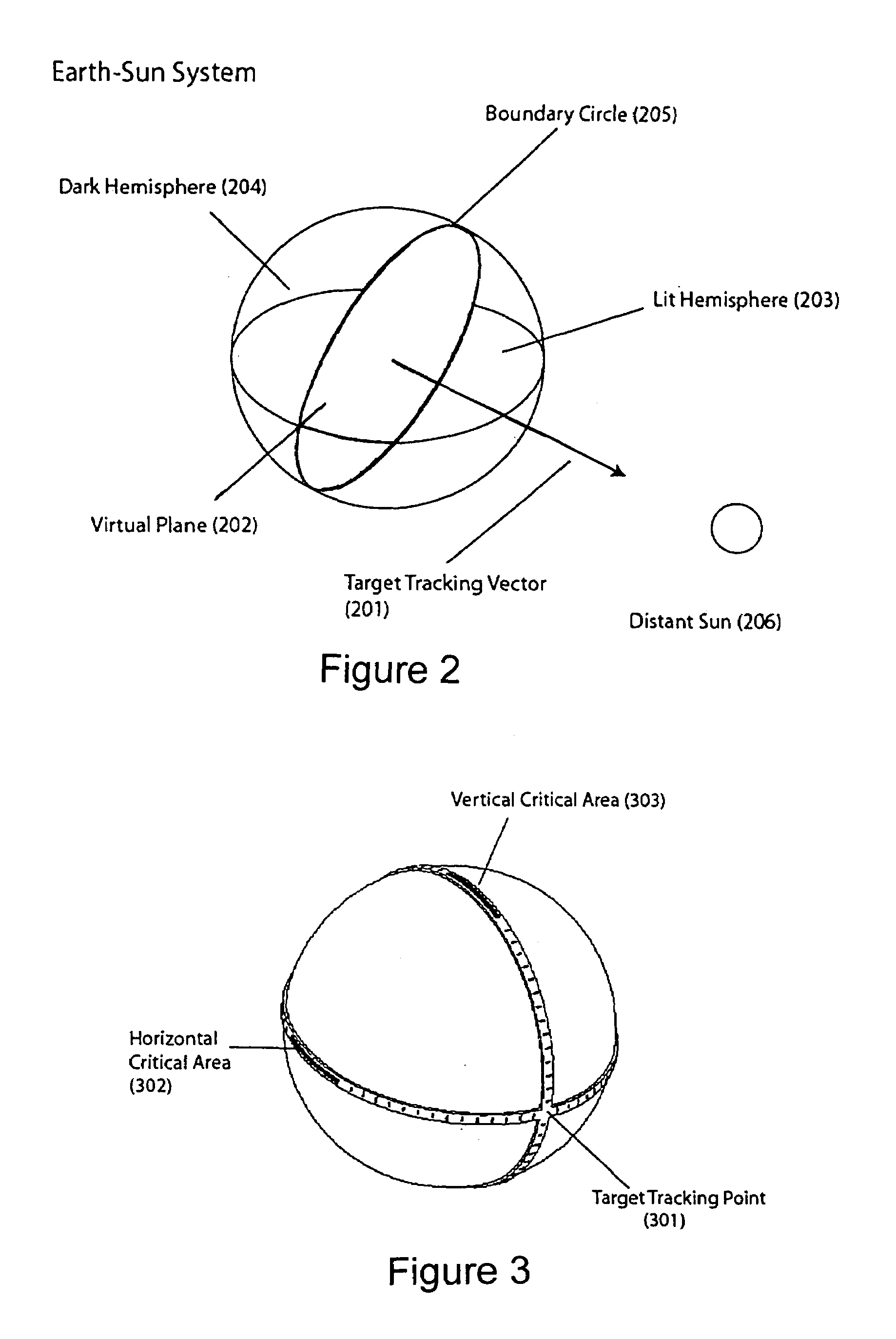
[0014]An object of the present invention is improved methods and apparatus for detecting and locating signals. A discrete three dimensional receiving element has multiple sensors surrounding the receiving element and detects the signal with those sensors generally facing the signal. The receiver then determines a boundary line around the surface of the receiving element, the boundary line generally separating the sensors that are detecting the signal from the sensors not detecting the signal. Then, a plane through the receiving element is drawn based upon the boundary line. The direction of the signal is determined based upon the plane. The apparatus may also determine the distance to the source of the signal based upon the strength of signal detected at the various sensors. If signal strength is measured, it is also used to more accurately determine the boundary line and plane.
[0015]The apparatus may also transmit a second signal, based upon the determined direction and / or distance to the source of the signal. This second signal might be the location of the source, and it could be communicated to a nearby vehicle for guidance, for example. Or, the second signal might be an electromagnetic beam pointed at the source. In this case, something would be determined about the source by the impinging of the beam on the source. For example, an infrared signal might make a “hot spot” on the source, which could be detected by the receiving unit or some other unit. Or, reflection of an EM wave could provide better ranging information.
[0016]As a feature, the receiver may have the capacity of rotating while the sensors are detecting the signal. This permits the use of fewer sensors and allows for alignment to the source.
[0020]The invention pertains to geometric sensor configurations and methods for use in electromagnetic systems. The invention offers an advanced geometric configuration for electromagnetic wave sensors that eliminates many of the problems associated with planar techniques. The underlying concept of the invention is based upon fundamental properties of radiation transmission and its reception on a spherical surface. Specifically, the technology exploits the principle that a point source of electromagnetic radiation will illuminate one hemisphere of a spherical object, leaving the other side in shadow (similar to the earth / sun system). The significance of this concept lies in the consistent and mathematically predictable position of the illuminated hemisphere relative to the radiating source. Consequently, by monitoring the illuminated hemisphere over the surface of a sphere, the relative 3D position of the point source can be calculated. Harnessing this concept, a spherical receiver can be constructed with strategically placed sensors to determine the position of the illuminated hemisphere and subsequently the three-dimensional location of the source.
[0021]The concept of monitoring a hemispherical surface can be designed into both passive (non-rotational) and rotational devices for a variety applications. An active rotational system can be designed with sensor bands that receive specific EM wavelengths associated with different signal sources. The active rotational system has benefits for beam steering, image acquisition, and reduced number of sensors, but will be limited by rotational slew rates. A passive sensor system can also be designed with an entire sphere covered with EM sensors. The passive sensor system has the benefit of no moving parts and multiple target tracking abilities, but requires more sensors and increased signal processing. The method used in monitoring electromagnetic wave systems is also applicable to many other wave propagating systems such as pressure waves, sonar waves, and particle sources. The technology stands to greatly benefit commercial industries involved with detection and sensing systems, astronomical instrumentation, remote sampling and measurement, target tracking and identification, wireless communications, security systems, and navigation systems.
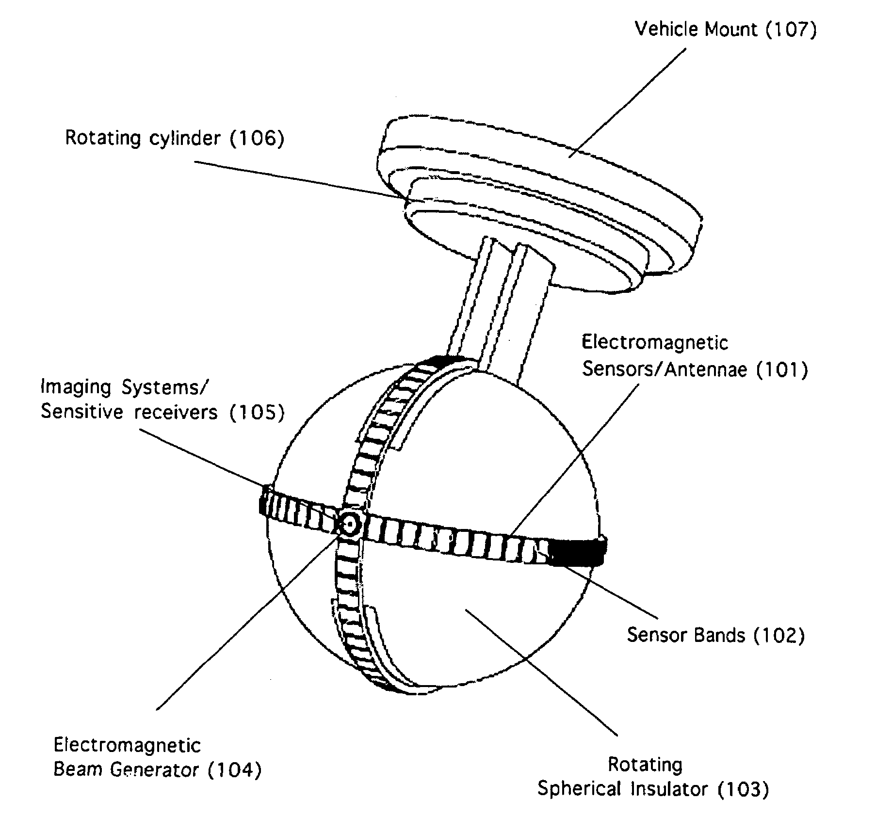
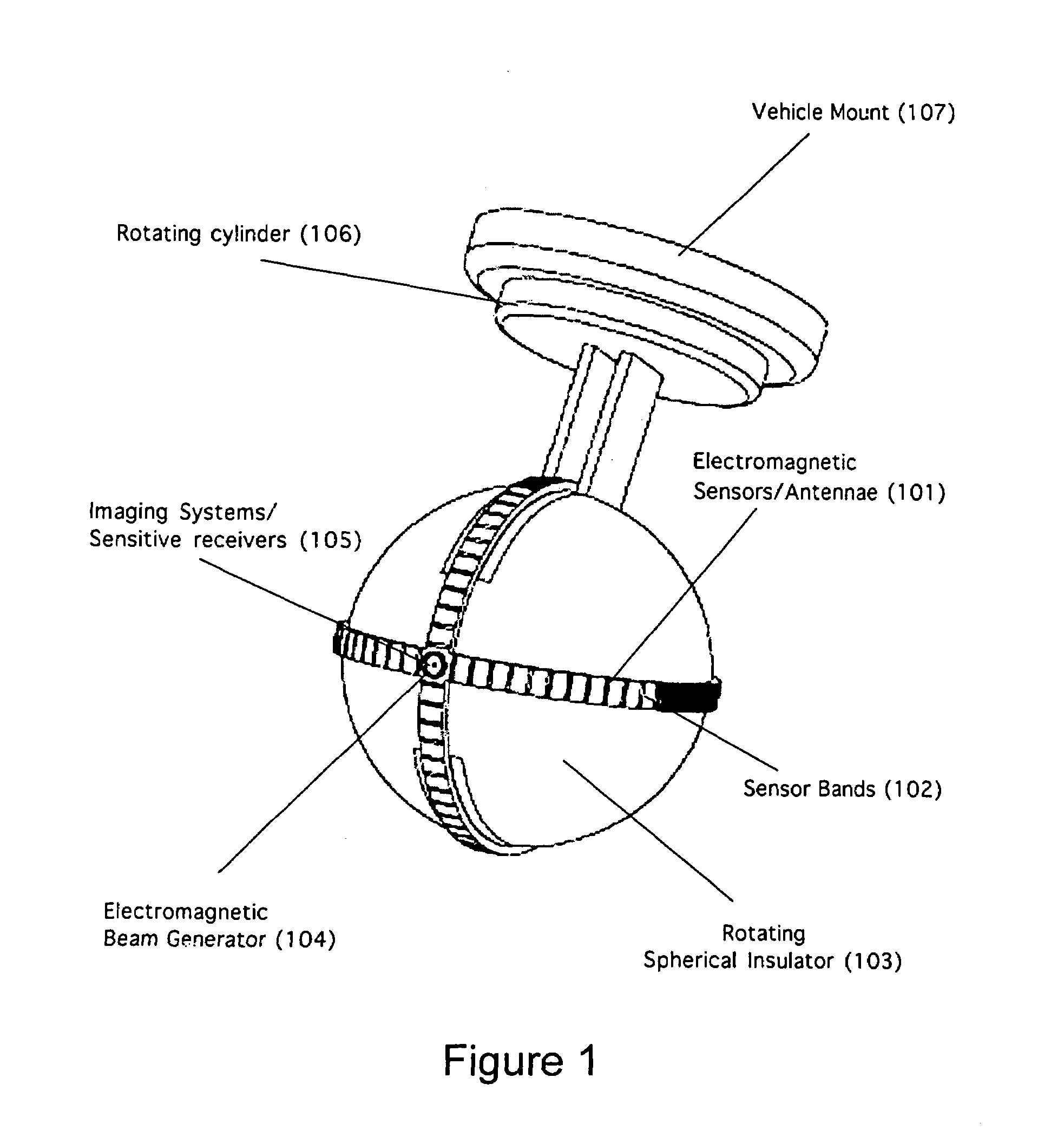
[0024]A third embodiment incorporates an active rotational system with passive EM sensors. This system incorporates the used of sensor bands with sensors concentrated in critical areas on the bands for precision angular turns. The system can be used to point highly sensitive receivers or imaging systems directly at an EM source. The system can accurately characterize EM sources by taking detailed images of the EM source. The system can also be used for pointing highly tuned wireless communication receivers for accurate data transmission.

Problems solved by technology

This method involves user-operated search patterns susceptible to human error and lengthy search times in emergency or time-critical scenarios.
The method susceptible to multi-path errors associated with reflecting waves from the surrounding environment.
These imaging systems are limited to a specific field of view (FOV) and incorporate scanning algorithms and image processing techniques for target tracking and identification.
The drawbacks of conventional imaging systems are detailed in The Handbook of Infrared Technology, “with a limited field-of-view system, a large distance is required to view a large area.
But then the target becomes very small and may be hard to find.
Shorter distances mean that a smaller area is viewed and overall search time is significantly increased.” These limitations on contemporary imaging systems cause significant difficulties when monitoring a wide field of regard for infrared sources.
In addition, sources which are near the 120° range of the system become obscured on the image plane and must be corrected with image processing algorithms.
The combination of wide FOV, focus time, image processing algorithms, and multiple sensors creates a complex, high-cost system with many components to determine the 3D location of an IR source.
Gaseous targets are notorious for scattering incoming beams and discouraging accurate analysis.
Planar techniques used to acquire the returned signals are prone to multi-path errors resulting from scattering.
Unintended reflecting objects will interfere with the analysis of intended objects.

Method used


Image

  • Apparatus and methods for detecting and locating signals
  • Apparatus and methods for detecting and locating signals
  • Apparatus and methods for detecting and locating signals

Examples


embodiment — 3d

Embodiment—3D Transmit Receive Scanning Systems

[0069]LIDAR systems using light wave frequencies can also be incorporated into the spherical receiving device. The system can emit various frequencies depending on the specific application. The receivers on the sphere will then collect waves returning from the reflecting object. Physical reflecting phenomenon such as Rayleigh and Raman scattering will be incorporated into the systems to determine the desired reflected wavelengths. In applications that search for specific gaseous particles, sensors will be used to receive the specific reflected frequency. The device will have the capability to scan various objects (including toxic, biological, and atmospheric) to find the size and density distribution. The size of the clouds will be derived by scanning and searching for boundary points where specific wavelengths (associated with reflecting particles) do not reflect back to the receiver. The density distribution of the cloud will be deter...


PUM


Abstract

A discrete three-dimensional receiving element has multiple sensors scattered over its surface to detect and locate a signal. The sensors facing the signal detect the signal, and a boundary line is drawn between the sensor which detect the signal and those which don't. The strength of signal may also be detected. A plane is drawn through the receiver element, and the direction of the signal is determined as generally perpendicular to the plane, in the direction of the sensors which are receiving the signal. Distance to the source may also be determined based on signal strength. The location of the signal source may be transmitted to a remote location, or the receiver may direct an electromagnetic beam toward the source to detect further information about the source.

Description

BACKGROUND OF THE INVENTION[0001]1. Field of the Invention[0002]The present invention is directed to methods and apparatus for detecting and locating signals. More specifically, the present invention is directed to methods and apparatus for detecting and locating signals with a three dimensional receiving element having sensors surrounding its surface.[0003]2. Description of the Related ArtOverall Methods to Locate EM in 3D[0004]Current methods to locate electromagnetic waves in three dimensions rely on intensity, wavelength and phase measurements using planar sensor arrays combined with signal and image processing algorithms. In lower frequency systems, measurements taken by planar sensor arrays are correlated to find the 3D location of electromagnetic wave sources. By measuring the phase shift of waves between sensors, the position of the source can be triangulated. Higher frequency systems in the visible light and infrared range typically use imaging system to determine 3D locati...

Claims


Application Information

Patent Timeline
Patent Type & Authority Patents(United States)
IPC IPC(8): G01S5/04G01C21/00G01D5/36
CPCG01S3/043G01S3/28G01S3/42G01S3/781G01S5/28G01S3/801G01S3/8034G01S5/12G01S5/16G01S3/783
Inventor RIEL, RYAN DAVIDCALIHMAN, ADAM ETHAN
Owner LUCID DIMENSIONS
Learn More