
Battery charger for portable devices and related methods

a portable device and battery technology, applied in the direction of power supply for data processing, transportation and packaging, liquid/fluent solid measurement, etc., can solve the problems of etc., to avoid damage to the portable device or the battery

Active Publication Date: 2007-09-18
MALIKIE INNOVATIONS LTD
View PDF12 Cites 78 Cited by
  • Summary
  • Abstract
  • Description
  • Claims
  • Application Information

AI Technical Summary

Benefits of technology

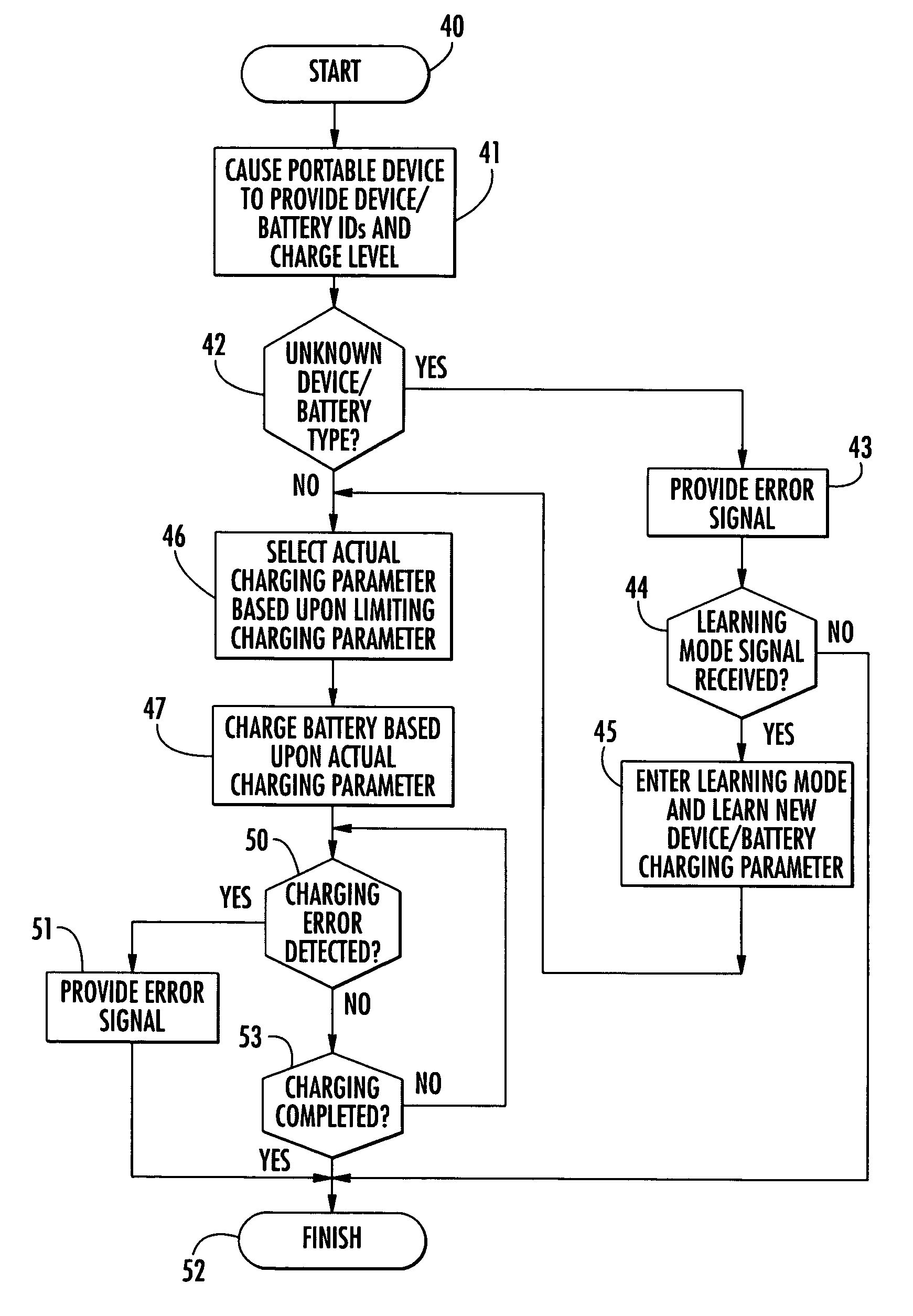
[0010]By way of example, a particular rechargeable battery may have a higher voltage and / or current limit associated therewith than the portable device it is carried by. In such case, charging the battery at its highest rated voltage / current level could cause damage to the portable device. Accordingly, the controller may select the actual charging parameter(s) based upon a limiting one of the different portable device and battery charging parameters. Thus, the controller may prevent the battery from being charged using a charging parameter that could damage either the portable device or the battery.
[0011]Moreover, the controller may also cause the portable device to identify a battery charge level of the rechargeable battery. Accordingly, the controller may further select the actual charging parameter(s) based upon the battery charge level. Thus, for example, the controller may select an actual charging parameter such as charging time based upon the charge level of the battery and a maximum charging time for the battery.

Problems solved by technology

In such case, charging the battery at its highest rated voltage / current level could cause damage to the portable device.
Thus, the controller may prevent the battery from being charged using a charging parameter that could damage either the portable device or the battery.

Method used


Image

  • Battery charger for portable devices and related methods
  • Battery charger for portable devices and related methods
  • Battery charger for portable devices and related methods

Examples


example

[0056]Turning now to FIG. 5, an exemplary portable or mobile device 1000 illustratively includes a housing 1200, a keyboard 1400 and an output device 1600. The output device shown is a display 1600, which is preferably a full graphic LCD. Other types of output devices may alternatively be utilized. A processing device 1800 is contained within the housing 1200 and is coupled between the keyboard 1400 and the display 1600. The processing device 1800 controls the operation of the display 1600, as well as the overall operation of the mobile device 1000, in response to actuation of keys on the keyboard 1400 by the user.

[0057]The housing 1200 may be elongated vertically, or may take on other sizes and shapes (including clamshell housing structures). The keyboard may include a mode selection key, or other hardware or software for switching between text entry and telephony entry.

[0058]In addition to the processing device 1800, other parts of the mobile device 1000 are shown schematically in...


PUM


Abstract

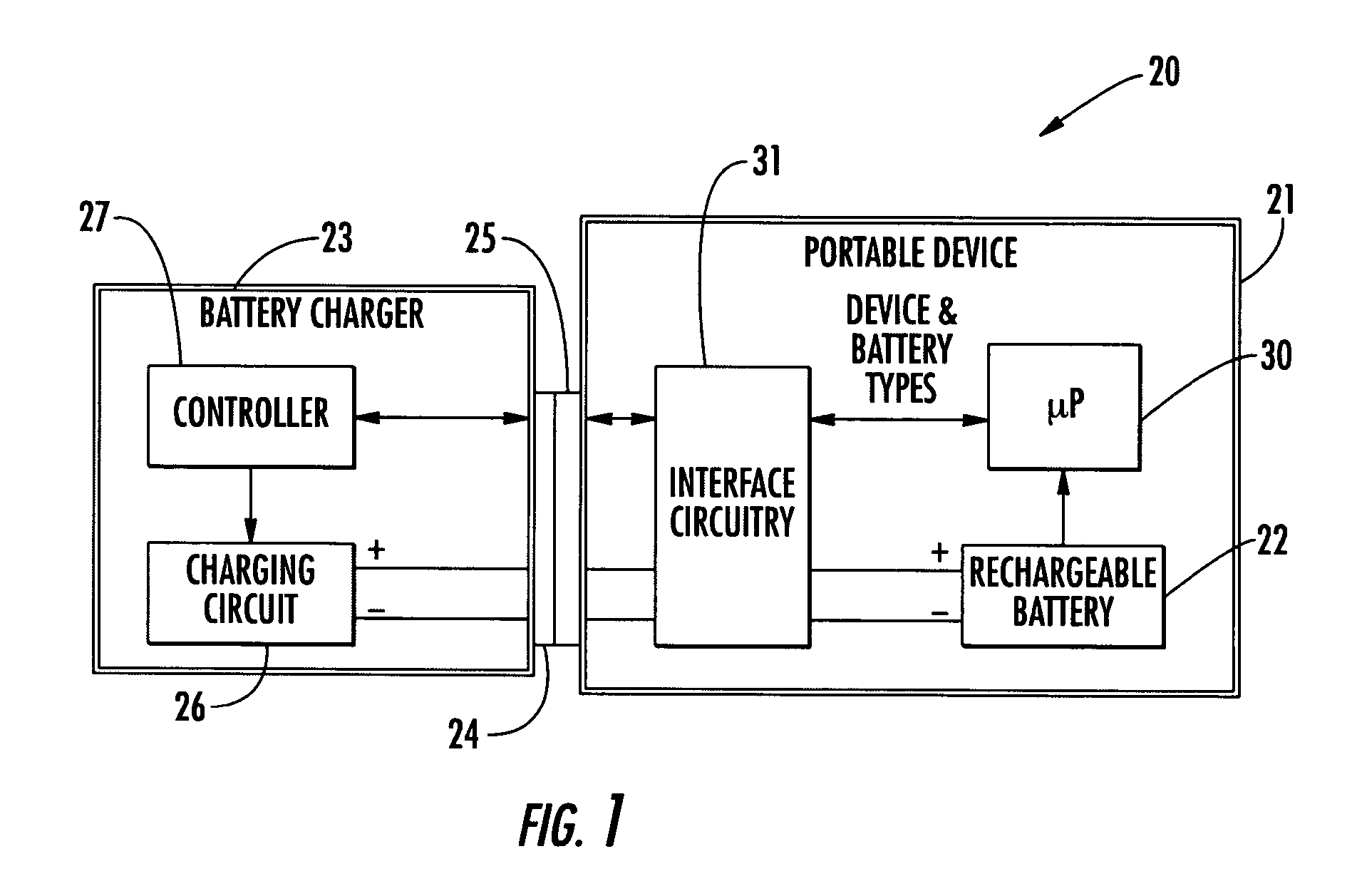
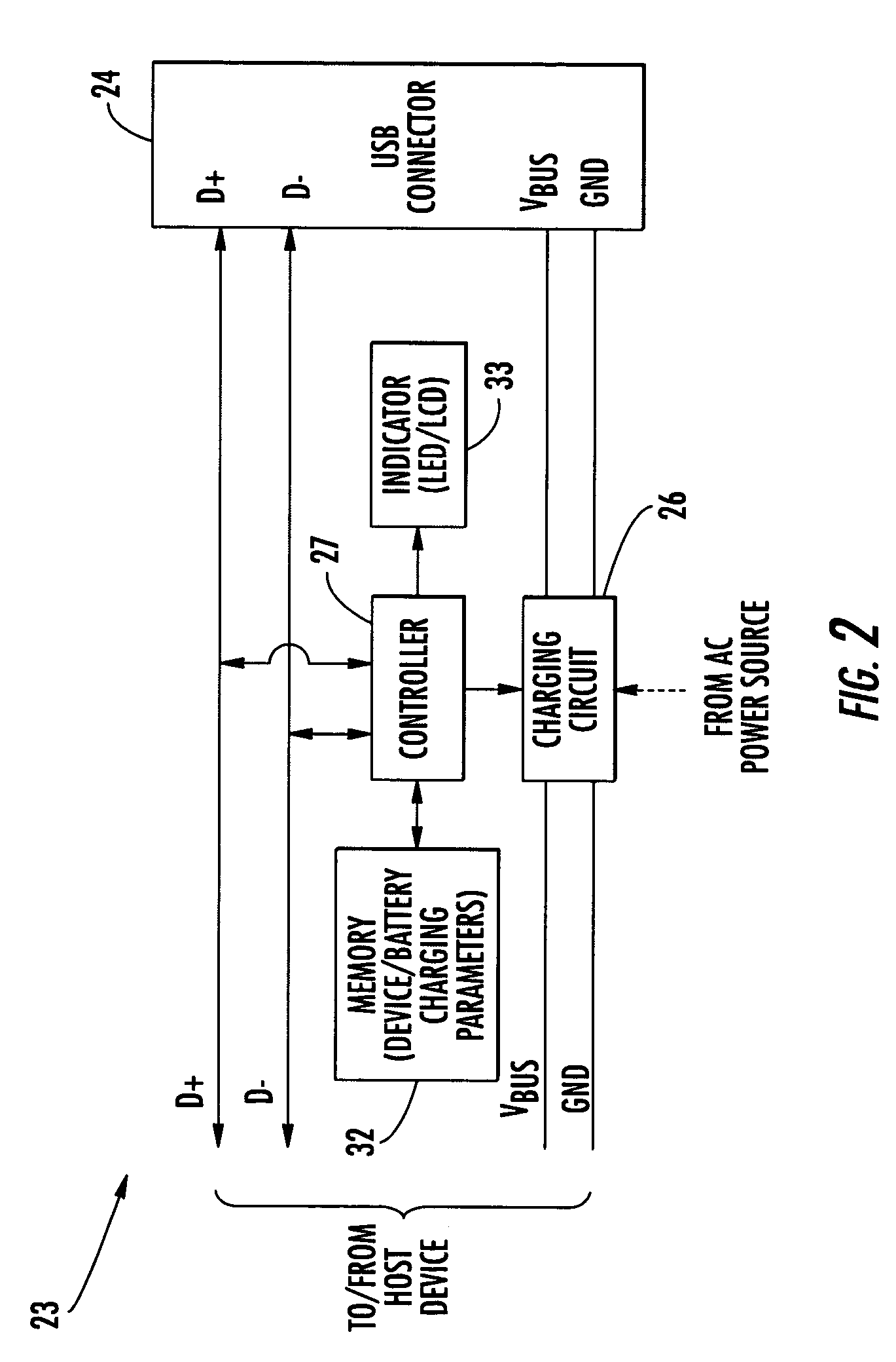
A battery charger may include a charger connector to be coupled to a corresponding device connector of a portable device including a rechargeable battery. The battery charger may also include a charging circuit connected to the charger connector, and a controller connected to the charger connector and the charging circuit. The controller may be for causing a portable device connected to the charger connector to identify its corresponding portable device type and its corresponding rechargeable battery type from among a plurality of different portable device types and different battery types, and for causing the charging circuit to charge the rechargeable battery based thereon.

Description

FIELD OF THE INVENTION [0001]The present invention relates to the field of battery-powered portable devices, and, more particularly, to battery chargers for such portable devices and related methods.BACKGROUND OF THE INVENTION[0002]Rechargeable batteries are used in a wide variety of portable devices such as laptop computers, cellular telephones, personal digital assistants (PDAs), etc. With the rapid increase in portable device technology, it is fairly common for users to replace their portable devices at frequent intervals. However, users may be required to also purchase new battery chargers when upgrading portable devices, because of different connector types or battery types used for different portable devices.[0003]In some cases, the use of standardized interfaces or connectors for portable devices allows a single battery charger to be used for charging different portable devices. For example, many portable devices now support the universal serial bus (USB) protocol, and includ...

Claims


Application Information

Patent Timeline
Patent Type & Authority Patents(United States)
IPC IPC(8): H02J7/00G06F1/26
CPCH02J7/0052H02J2007/0062H02J2007/006H02J2207/30H02J7/00
Inventor PURDY, MICHAEL L.BAYNE, RYAN MITCHELL
Owner MALIKIE INNOVATIONS LTD
Learn More