Slide device

a technology of sliding device and sliding plate, which is applied in the direction of convertible stools, chairs, furniture parts, etc., can solve the problems of laborious correction

Inactive Publication Date: 2007-09-11
TOYOTA SHATAI KK
View PDF21 Cites 16 Cited by
  • Summary
  • Abstract
  • Description
  • Claims
  • Application Information

AI Technical Summary

Benefits of technology

[0008]In the first invention, the slide construction of sandwiching the first-type rail member forming the space open sideways and the second-type rail member positioned in the space in such a way that both rail members are movable relative to each other by the resistance-reducing member is applied to the movable-side rail member and the fixed-side rail member supporting the movable-side rail member to support the slide plate slidably relative to the base member. Therefore compared with the construction in which balls serving as the resistance-reducing member are interposed between side surfaces of opposed rail members, the slide device of the first invention displays a sufficient degree of durability against a offset load applied in such a way as to vertically shift the movable-side rail member and the fixed-side rail member from each other. Consequently it is unnecessary to cut or quench guide grooves and save labor for correcting them required in use. Because the slide construction is provided at both side parts of the slide plate, it is possible to assemble the slide device in advance at places other than an assembling line without performing a work of installing cross members while making accurate adjustment of parallelism between left and right rails.
[0027]In the fourteenth invention, a ball is inserted into the ball-holding opening by elastically expanding the aperture of the ball-holding opening. As a result, the aperture returns to the original shape and prevent the ball from escaping from the ball holding opening. In this state, the ball is rotatably held in the ball holding opening with a portion of the ball exposed from the apertures.

Problems solved by technology

Consequently it is unnecessary to cut or quench guide grooves and save labor for correcting them required in use.

Method used


Image

  • Slide device
  • Slide device
  • Slide device

Examples


first embodiment

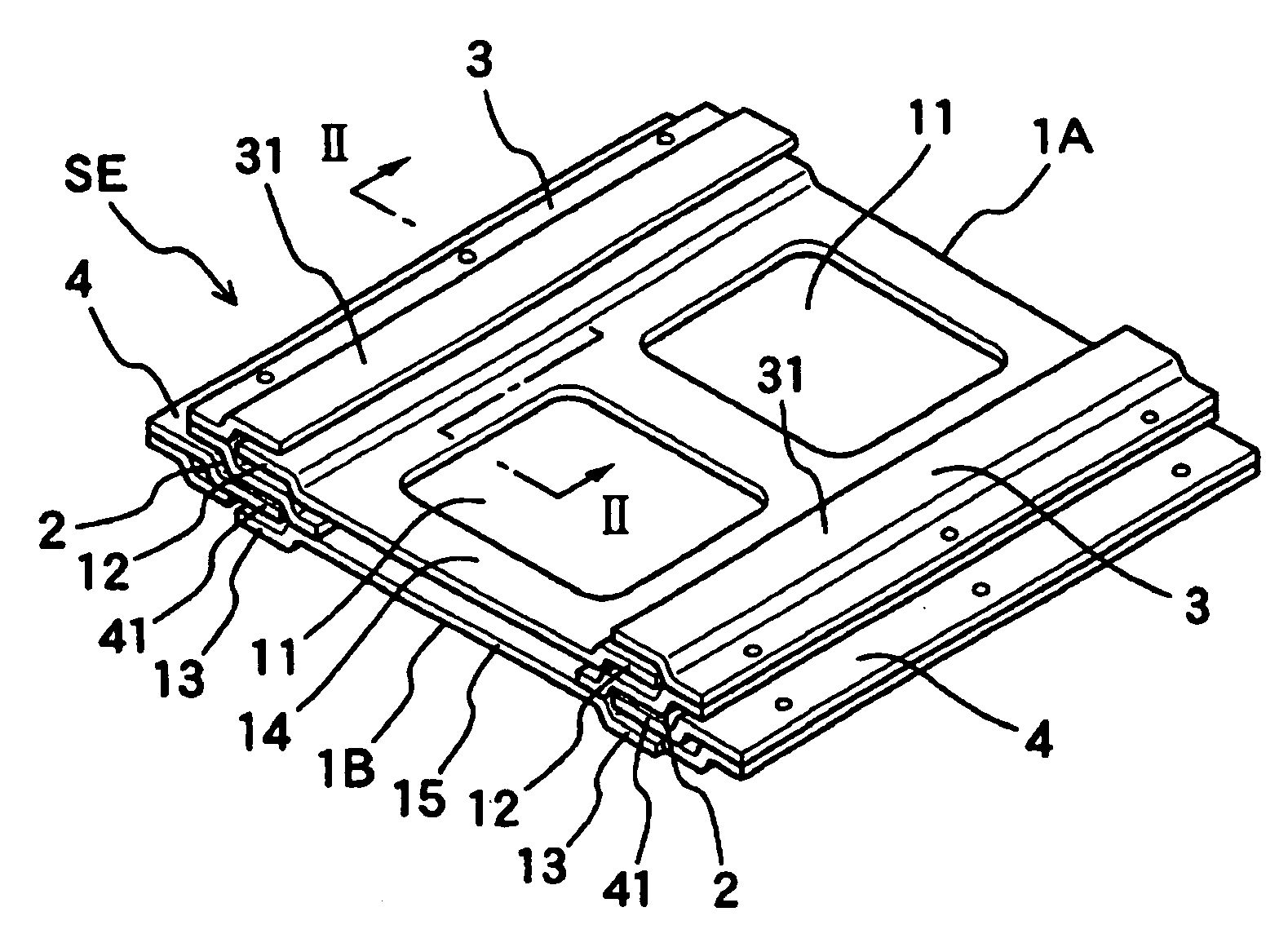
[0039]FIG. 1 shows the outlook of a slide device SE. The slide device SE has two rectangular slide plates 1A, 1B disposed vertically and parallel with each other. A rectangular hole 11 for making the slide device SE lightweight is formed at front and rear positions of a central part of each of the slide plates 1A, 1B. Both side parts 12, 13 (only one side part is shown in FIG. 2) of the lower slide plate 1B and the upper slide plate 1A curve upward or downward from general parts 14, 15 respectively and extend horizontally in a constant width. The slide plates 1A, 1B are formed in the same configuration by press molding and symmetrically disposed at upper and lower positions by inverting one slide plate. The side part 12 of the slide plate 1A serves as a rail member L1 which is a second-type rail member and a movable-side rail member. The side part 13 of the slide plate 1B constitutes a part of a rail member L3 which is described later.

[0040]A connection plate 2 is fixed to an edge o...

second embodiment

[0048]In the first embodiment, two slide plates, namely, the upper and lower slide plates are provided. But three or more side plates can be provided. FIG. 6 shows a schematic construction of a slide device having four slide plates. In FIG. 6, illustration of balls is omitted. In FIG. 6, four slide plates 1C through 1F are arranged vertically in an approximately horizontal posture. With the connection plate 2, the hold-down plate 3, and side parts of the slide plates 1C through 1F, rail members L6 through L11 forming U-shaped spaces open toward the inner and outer sides of the slide device SE are formed. These members are so disposed that they overlap each other in the vertical direction. In the rail members L7 through L10, an upper side 30 and a lower side 10 of one rail member penetrate into the U-shaped space of the other rail member. The upper sides 30 and the lower sides 10 constitute second-type rail members. The rail members L8, L10, provided on the slide plates 1E, 1F respec...

third embodiment

[0049]FIG. 7 shows a sectional view of main parts of a slide device. In FIG. 7, a fixed-side rail member (only one fixed-side rail member is shown) 60 of the slide device is constructed by connecting an upper rail 601 and a lower rail 602 to each other. That is, a long plate is formed by press molding to form the upper rail 601 and the lower rail 602. Half parts 6012 and 6022 extending approximately horizontally are bent vertically upward and downward from half parts 6011 and 6021 respectively at approximately the center of the upper rail 601 and the lower rail 602 in the widthwise direction of the rail. Thus the upper rail 601 and the lower rail 602 have the same configuration in section. The half parts 6011 and 6021 are butted against each other with the half parts 6011 and 6021 located symmetrically and vertically. The half parts 6011 and 6021 are fixedly connected to a bracket M2 on a floor F with a bolt M1 penetrating through the half parts 6011 and 6021 vertically. On an oppos...


PUM


Abstract

A slide device, comprising first class members having spaces opening to sides formed in the longitudinal directions thereof and second class rail members positioned in the spaces, wherein either of the first and second class rail members movable relative to each other are formed in movable rail members and the other are formed in fixed rail members, the movable rail members are installed at both side parts of slide plates, the slide plates are positioned on brackets parallel with each other, and the movable rail member installed on the slide plate is supported by the fixed rail member installed on the slide plate.

Description

TECHNICAL FIELD[0001]The present invention relates to a slide device and more particularly to improvement of the construction of the slide device preferable for use in a slide seat to which a high offset load is applied and which is used by a physically handicapped person in getting on and off a vehicle.BACKGROUND ART[0002]FIG. 8 shows the outlook of a van-type vehicle having a slide seat which is used by the physically handicapped person when the physically handicapped person gets on and off the vehicle. A slide door SD at a side surface of the vehicle is opened so that a seat ST for the vehicle is advanced to a lower position, near a road surface, outside the vehicle by a slide device SE. As shown in FIG. 9, the slide device SE is constructed of a pair of parallel outer rails 101 disposed outermost, a pair of parallel middle rails 102 disposed inward from the outer rails 101, and a pair of parallel inner rails 103 disposed inward from the middle rails 102. The left and right middl...

Claims


Application Information

Patent Timeline
Patent Type & Authority Patents(United States)
IPC IPC(8): F16M13/00A47B88/493B60N2/06B60N2/07B60N2/14B60N2/24
CPCB60N2/062B60N2/0715B60N2/0737B60N2/0747B60N2/14B60N2/245B60N2/06
Inventor KATO, HISAYOSHITANIGUCHI, KAZUYUKIIWATANI, MASAMITSUMIURA, YOSHIYUKI
Owner TOYOTA SHATAI KK
Why Eureka
Try Eureka