
Electrostatic precipitator

a precipitator and electrostatic technology, applied in the direction of colloidal chemistry, transportation and packaging, electric supply techniques, etc., can solve the problem of impaired dust precipitation efficiency

Inactive Publication Date: 2007-08-28
SETABU ANZAI
View PDF14 Cites 15 Cited by
  • Summary
  • Abstract
  • Description
  • Claims
  • Application Information

AI Technical Summary

Problems solved by technology

When the resistance is changed in normal operation range, dust precipitation efficiency may be impaired in some conditions.

Method used


Image

  • Electrostatic precipitator
  • Electrostatic precipitator
  • Electrostatic precipitator

Examples


Embodiment Construction

[0019]Reference will now be made to the drawings, wherein like numerals refer to like parts throughout. The present teachings relate to an electrostatic precipitator for improving electrostatic precipitation efficiency.

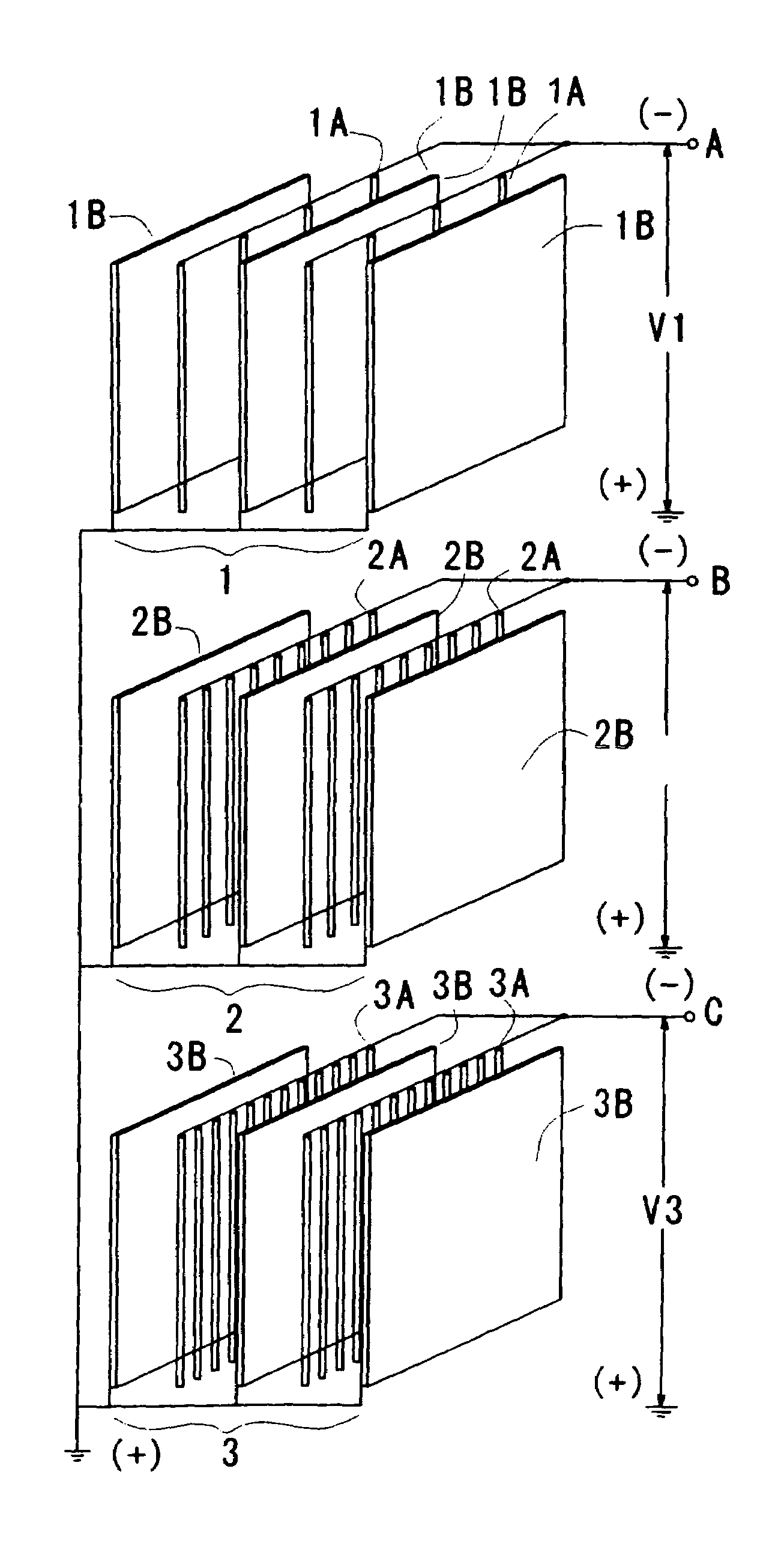
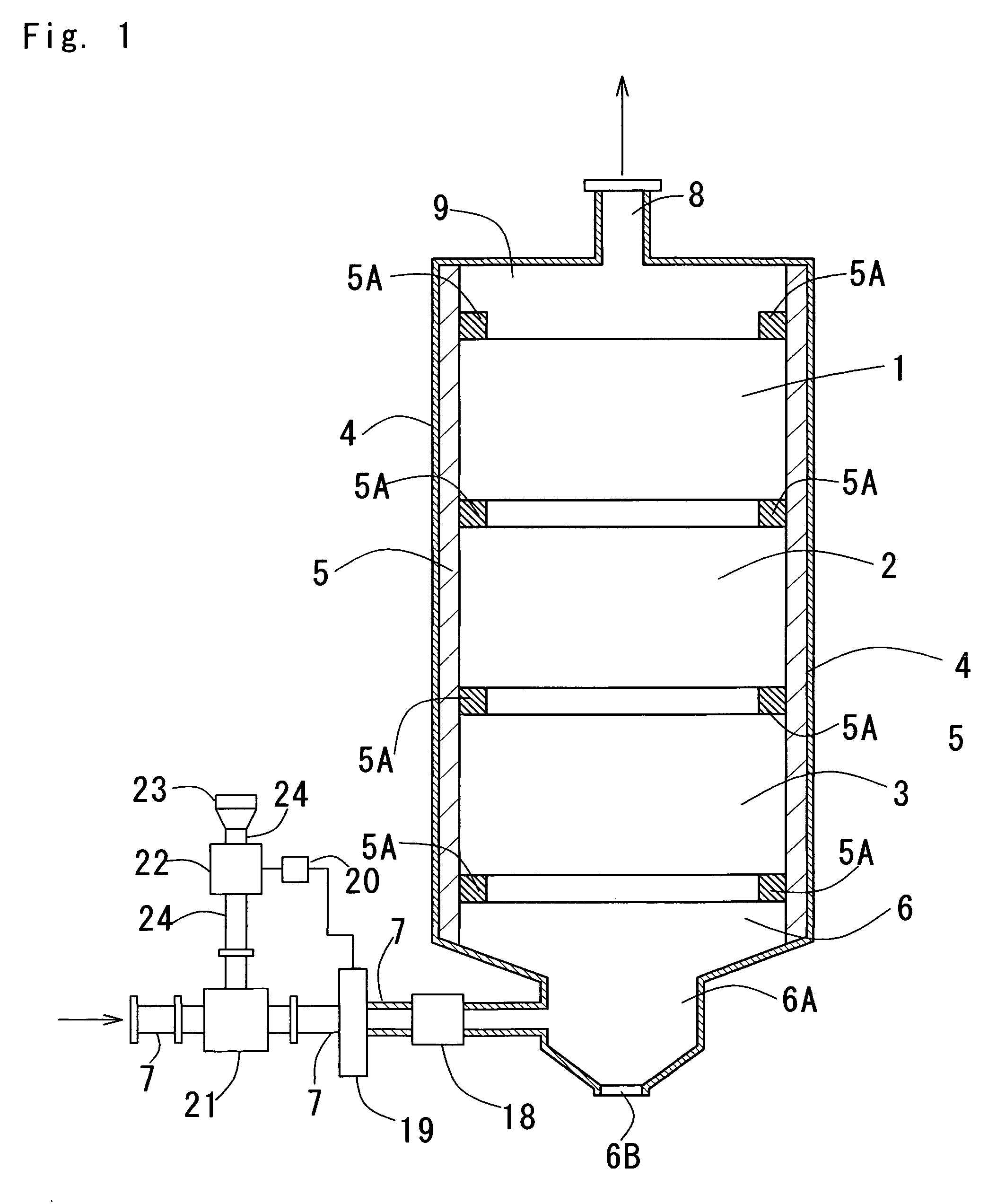
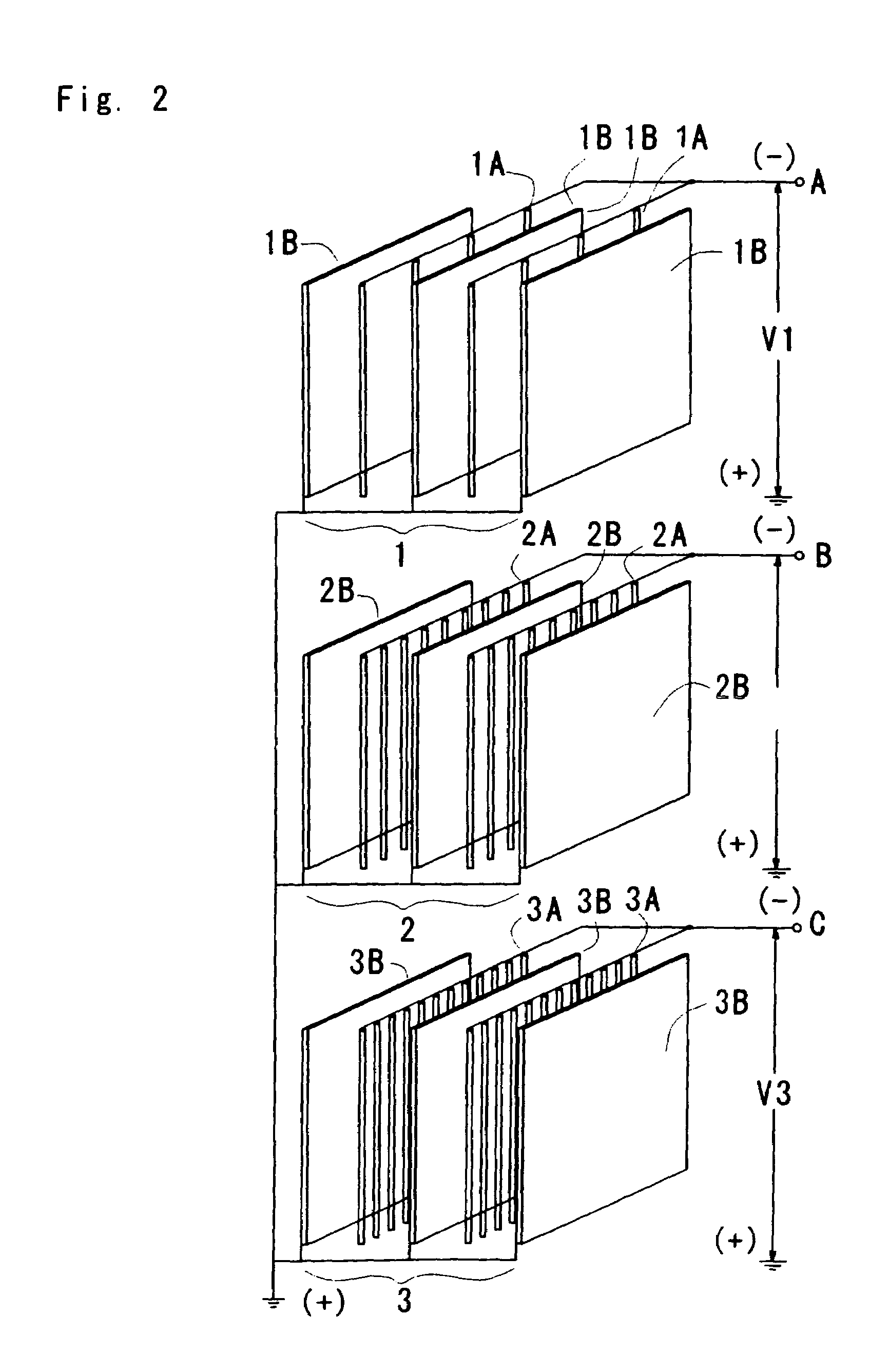
[0020]FIG. 1 shows a sectional view of an electrostatic precipitator 4 comprising electrical insulation material 5 attached to an interior portion or wall thereof and a plurality of electrostatic precipitation units 1, 2, 3 vertically arranged therein. The electrostatic precipitation units 1, 2, 3 are fixedly attached to the electrical insulation material 5 via mounting components 5A.

[0021]In operation, exhaust gas enters the electrostatic precipitation device 4 via an exhaust gas intake pipe 7 and passes therethrough into an interior region 6 of the electrostatic precipitation device 4. From there, as shown in FIG. 1, the electrostatic precipitation device 4 is arranged so that the flow of exhaust gas sequentially passes through the electrostatic precipitation units ...


PUM


Abstract

An electrostatic precipitator having a plurality of electrostatic precipitation units positioned within the electrostatic precipitator. Each of the electrostatic precipitation units includes a plurality of negative wire electrodes and a plurality of positive electrode plates. The electrostatic precipitation units are arranged such that spacing between the negative wire electrodes of a first electrostatic precipitation unit is a first distance apart, and spacing between the negative wire electrodes of additional electrostatic precipitation units is less than the spacing between the negative wire electrodes of the first electrostatic precipitation unit. Moreover, a variable voltage is applied to the each of the electrostatic precipitation units between the positive electrode plates and the negative wire electrodes so as to cause particles in the exhaust gas to adhere to the positive electrode plates.

Description

BACKGROUND OF THE INVENTION[0001]1. Field of the Invention[0002]The present invention relates to electrostatic precipitation technology and, in particular, to an electrostatic precipitator.[0003]2. Description of the Related Art[0004]Conventional electrostatic precipitator clean exhaust gas by applying a high voltage between two electrodes (+) and (−) which causes particles in the exhaust gas to be deposited on the (+) electrode. For a constant voltage, the electrical resistance between the electrodes of (+) and (−) varies with the quantity of particles in the exhaust gas. When the resistance is changed in normal operation range, dust precipitation efficiency may be impaired in some conditions. For example, an electrical short may occur at low resistance depending on the quantity of dust in the electrostatic precipitator and / or on the (+) electrode.[0005]There currently exists a need to continuously conduct particle precipitation within the normal operation range irrespective of the...

Claims


Application Information

Patent Timeline
Patent Type & Authority Patents(United States)
IPC IPC(8): B03C3/68
CPCB03C3/025B03C3/41B03C3/47B03C3/68Y10S323/903Y10S55/01
Inventor KATAYAMA, HIDEO
Owner SETABU ANZAI
Learn More