
System and method for distributing module phase information

a technology of phase information and module, applied in frequency-division multiplex, dc-ac conversion without reversal, instruments, etc., can solve the problem of difficult module phase information distribution and clock information

Active Publication Date: 2007-08-21
TEXAS INSTR INC
View PDF3 Cites 14 Cited by
  • Summary
  • Abstract
  • Description
  • Claims
  • Application Information

AI Technical Summary

Benefits of technology

The present invention provides a data transmission and addressing protocol between modules to process clock and phase information. The use of a clock input / output stream and a resistor network allows for easy addressing of modules without the need for circuit changes. The master-slave configuration allows for self-configuration of module addresses as new modules are added or removed from the power system. The technical effects of this invention include improved efficiency and flexibility in data transmission and addressing between modules.

Problems solved by technology

One challenge in maintaining synchronous offset phases among the modules stems from the flexibility of the multi-module DC-DC converter.
In particular, if modules are constructed to be swapped in and out of a system, or ganged together to meet the demands of a power application, distribution of the clock and phase information among the modules becomes extremely difficult, since there is a lack of knowledge of the arrangement of the modules.

Method used


Image

  • System and method for distributing module phase information
  • System and method for distributing module phase information
  • System and method for distributing module phase information

Examples


Embodiment Construction

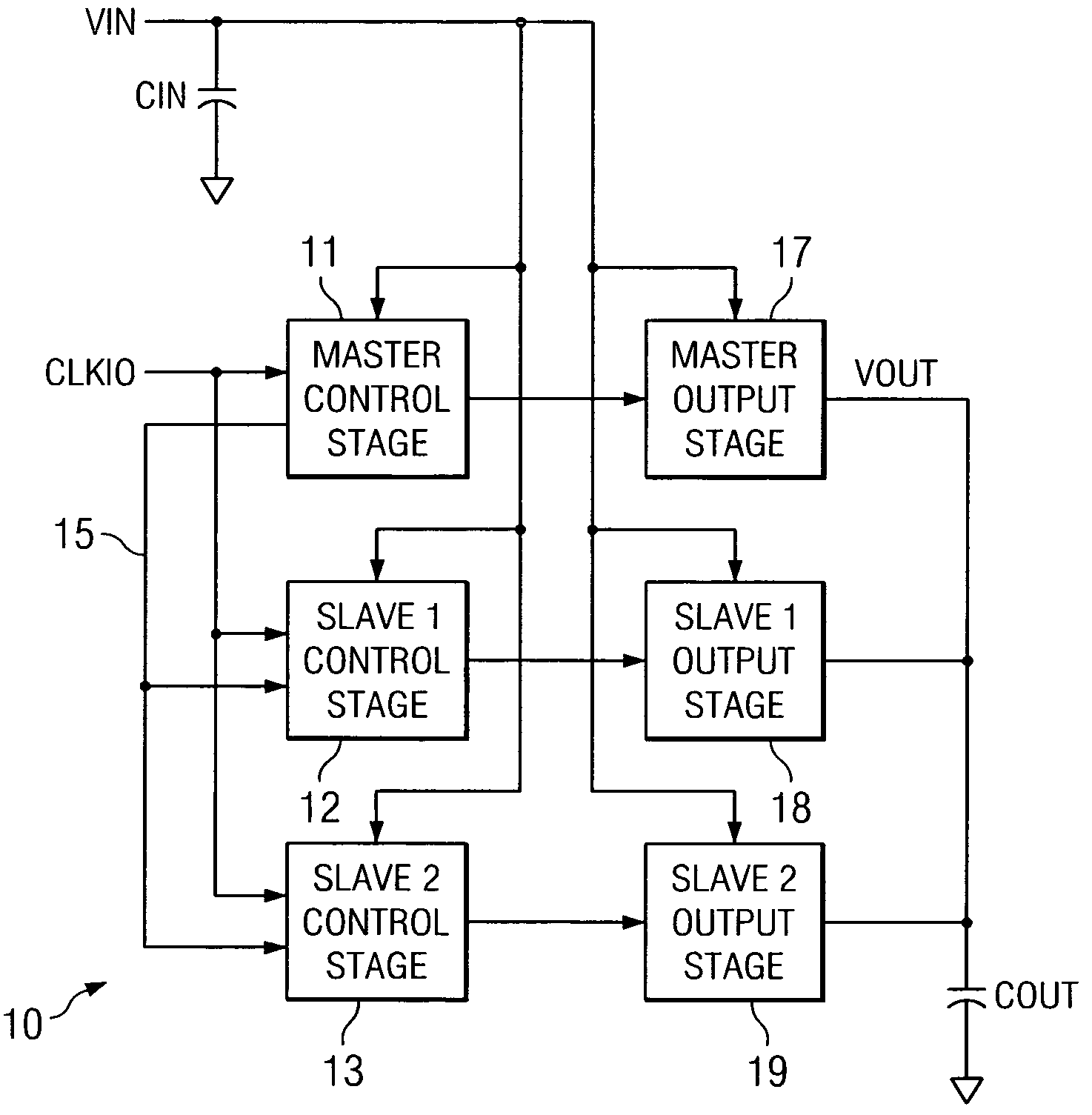
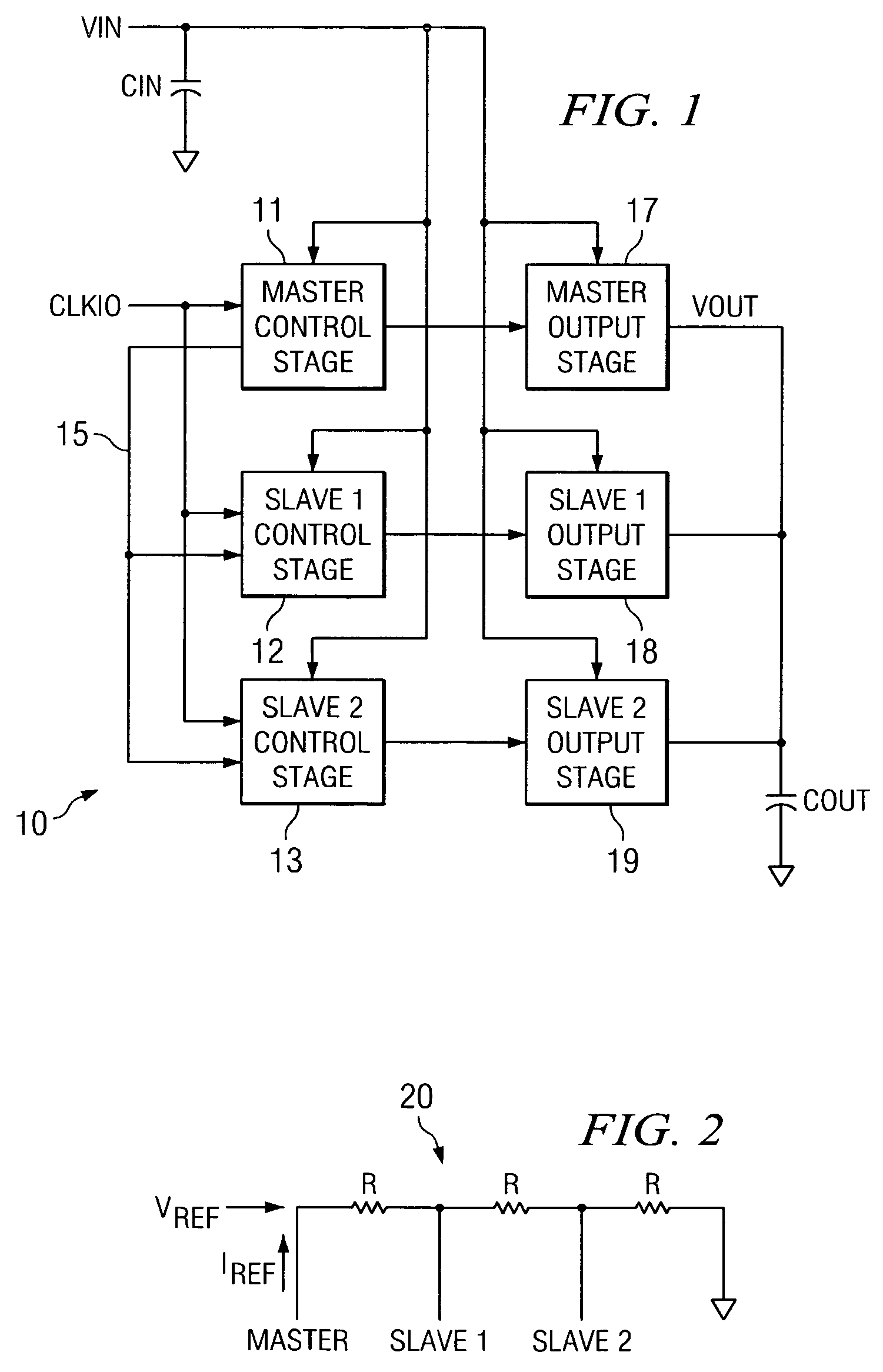
[0019]Referring now to FIG. 1, an exemplary embodiment of a multiple module DC-DC converter is illustrated in block diagram form as converter 10. Converter 10 is illustrated as a three-module converter, in which the output stages are operated out of phase by 120°. A number of different phases can be realized with this type of multiple module DC-DC converter, with the phase separation being adjusted appropriately. In accordance with the present invention, any number of phases or modules can be accommodated in producing a multiple module DC-DC converter.

[0020]Converter 10 consists of three different control stages, 11-13, for three different output stages 17-19. Control stages 11-13 drive respective output stages 17-19 out of phase with each other to achieve a reduced ripple current on input VIN as well as a reduced output current for output VOUT. With a reduced ripple current on the input and output, capacitors CIN and COUT can be reduced in size or rating to significantly reduce cos...


PUM


Abstract

A multi-module DC-DC converter provides synchronization between modules based on identification of a module within a chain. A resistor network can be used for the chain so that each module obtains a particular voltage based on its position within the chain. A master module provides a source current to drive the chain so that each module can determine its relative position in the chain based on voltage readings. With this configuration, a master module can determine how many modules are in the chain, and each slave module can determine its relative position in the chain. The module information contributes to synchronization between the modules for use in current ripple cancellation, for example, in the multi-module DC-DC converter.

Description

CROSS REFERENCE TO RELATED APPLICATIONS[0001]N / ASTATEMENT REGARDING FEDERALLY SPONSORED RESEARCH OR DEVELOPMENT[0002]N / ABACKGROUND OF THE INVENTION[0003]1. Field of the Invention[0004]The present invention relates generally to distributing phase information among a number of controllers and relates more particularly to distributing clock phase information among multiple controllers for appropriate synchronization.[0005]2. Description of Related Art[0006]DC-DC converters supply power in a variety of applications, including modular power supplies. Computer or digital equipment applications often call for DC-DC power converters capable of handling widely varying loads. Solutions for these applications sometimes involve specifying large capacity power converters, or high performance power converters. One flexible solution relates to a power converter arranged as a group of modules where modules may be added or removed to meet power specifications.[0007]One goal in providing a power to a...

Claims


Application Information

Patent Timeline
Patent Type & Authority Patents(United States)
IPC IPC(8): G08B21/00
CPCH02J1/102
Inventor WIKTOR, STEFAN W.LI, XUENING
Owner TEXAS INSTR INC
Learn More