
Printers with positional sensors

a position sensor and printer technology, applied in the field of printers, can solve the problems of inconvenient use of printers on other floors of users' unfamiliarity, inability to ensure the sufficient facilities of larger-scaled networks, and difficulty in managing and maintaining the system

Inactive Publication Date: 2007-08-14
SEIKO EPSON CORP
View PDF20 Cites 44 Cited by
  • Summary
  • Abstract
  • Description
  • Claims
  • Application Information

AI Technical Summary

Benefits of technology

[0014]The object of the present invention is thus to provide a technique that enables a user or an apparatus to utilize any of printers connected to even a large-scaled network without applying any additional load to a network manager.

Problems solved by technology

The conventional remote printer technique generally treats a relatively small-scaled network, for example, on one floor in a building, but does not ensure the sufficient facility in larger-scaled networks.
It is, however, rather inconvenient to use printers on other floors which the user is unfamiliar with, since the user does not know the actual installation positions of the available printers on the network.
The conventional remote printer technique, however, collectively manages the database and thereby has difficulties in management and service of the system.
This requires much labor of the network manager when a large number of printers are connected to the network.
This requires much labor and time for the management.
Similar problems arise in the arrangement where the user of each printer carries out the registration.
The insufficient management of the positions of the respective printers may cause the user who has selected a desired printer for printing on the map not to find the desired printer at the registered position, and may require much time and labor for the user to receive the resulting prints.
The centralized management of the positions of the respective printers by a management section, on the other hand, does not allow the flexible change of the layout on each floor.
Specification of the position of the printer by the name of the building or by the name of the section or the division is rather inconvenient in the event of reorganization or restructuring.
This series of procedure is rather complicated.
Such improvement and development are, however, not sufficient for the efficient use of the plurality of printers connected to the large-scaled network as discussed previously.
The directory service, however, does not inform the user of the position of the printer, for example, which is closest to the computer that requires printing.
It is, however, extremely troublesome to obtain the information regarding which printer is the closest.
This possible application is, however, not practical so far since it is difficult to specify printers that are present in the route of commuting.

Method used


Image

  • Printers with positional sensors
  • Printers with positional sensors
  • Printers with positional sensors

Examples


Embodiment Construction

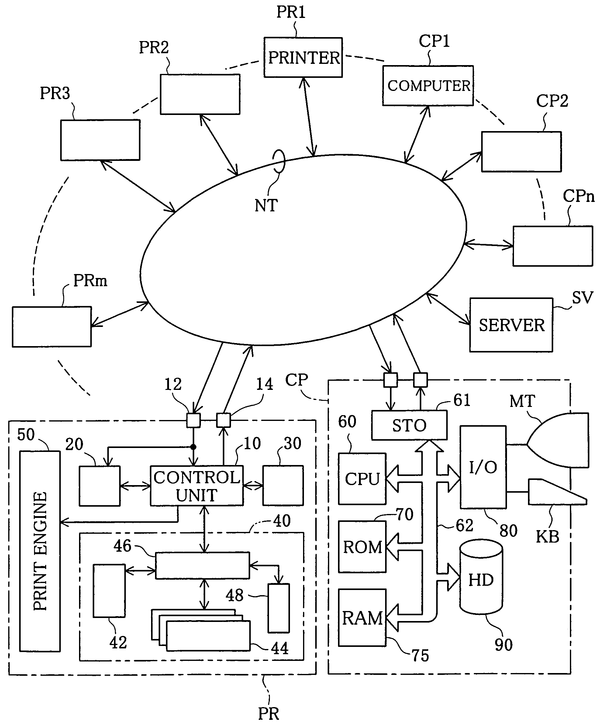
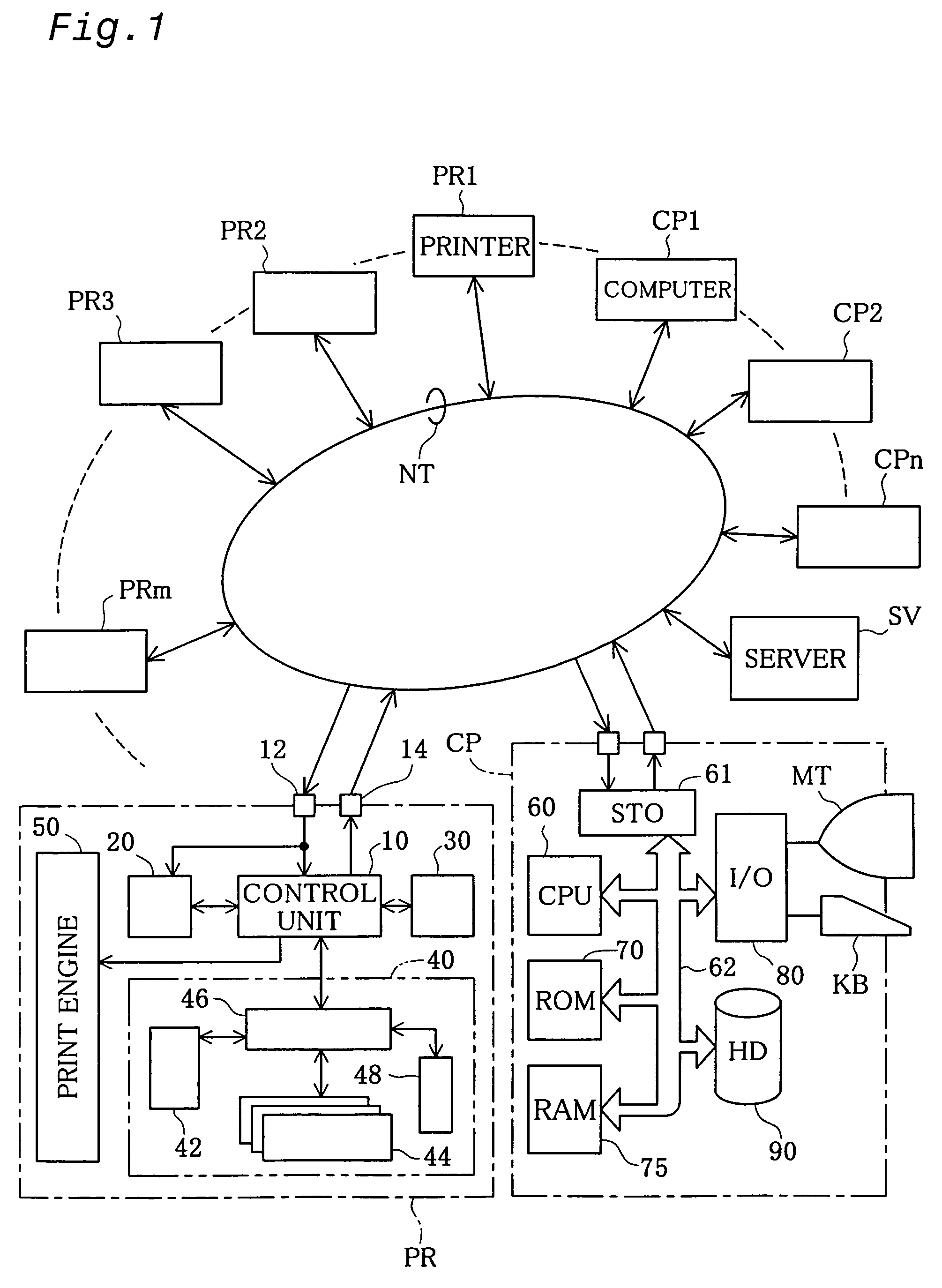
[0065]FIG. 1 is a block diagram illustrating a network NT in one embodiment according to the present invention. The network NT shown in FIG. 1 is formed by a number of computers CP1 through CPn (n is an arbitrary natural number), a number of printers PR1 through PRm (m is an arbitrary natural number), and a network server (hereinafter simply referred to as the server) SV having the functions of a printer server. The server SV manages the computers CP and the printers PR connected to the network NT using IP addresses. Whenever each of the computers CPn and the printers PRm is connected to the network NT with a supply of power, an intrinsic IP address is allocated to the computer CPn or the printer PRm by the server SV. Each computer CPn that requires printing outputs the print data to a desired printer PRm managed by the server SV. The server SV once spools the output print data and successively outputs the print data to the desired printer PRm, so as to cause printing to be carried ...


PUM


Abstract

The technique of the present invention ensures efficient management of printers in a large-scaled network even under a condition that some printer shifts its position on the network. A positioning unit included in each printer connected to the network recognizes positional information, which represents its own geographical position where the printer is located and includes, for example, a latitude and a longitude. Each of computers connected to the network obtains the positional information from each of the printers and specifies a printer, to which print data are output to carry out printing, based on the positional information thus obtained. This arrangement extremely facilitates the management of the printers on the network and enables the user to carry out printing with a selected printer that is located at a desired position.

Description

BACKGROUND OF THE INVENTION[0001]1. Field of the Invention[0002]The present invention relates to a printer that receives print data from a printing control apparatus, such as a computer, and executes printing, as well as a printing control apparatus that is suitably applied for the printer. More specifically the present invention pertains to a technique that selects an optimum printer to execute printing in a system where at least one printer and at least one printing control apparatus are connected via a network.[0003]2. Description of the Related Art[0004]In a system where a plurality of printers are linked on a network, a technique called remote printer is applied to select an arbitrary printer on the network and cause the selected printer to execute printing without directly connecting respective printing control apparatuses, such as computers, with the plurality of printers. The remote printer technique is actualized by a diversity of applications. One possible application conn...

Claims


Application Information

Patent Timeline
Patent Type & Authority Patents(United States)
IPC IPC(8): G06F15/00G06K1/00B41J29/38G06F3/12G06F13/00H04L12/24
CPCG06F3/1204G06F3/1231G06F3/1288H04L41/12
Inventor HANAOKA, MASAAKI
Owner SEIKO EPSON CORP
Learn More