Ratchet arrangement for a chain splitter

a chain splitter and ratchet technology, applied in the direction of wrenches, multi-purpose tools, manufacturing tools, etc., to achieve the effect of convenient storage and transportation

Inactive Publication Date: 2007-08-14
HUANG HONG JHEN
View PDF7 Cites 11 Cited by
  • Summary
  • Abstract
  • Description
  • Claims
  • Application Information

AI Technical Summary

Benefits of technology

[0007]The primary objective of the present invention is to provide a ratchet arrangement for a chain splitter, wherein the chain splitter is compact for easy storage and transport, and the rotating rod can move axially with respect to the splitter body simply by turning the ratchet wrench a small angle.
[0008]To achieve the abovementioned objective, a threaded rod integrally formed at a side of a ratchet wrench is screwed in the threaded hole of the splitter body. Rather than rotating over 360 degrees, the ratchet wrench only rotates within a small angle, and substantially reduces the rotation-caused oscillation.

Problems solved by technology

However, this conventional chain splitter still has the following disadvantages:

Method used


Image

  • Ratchet arrangement for a chain splitter
  • Ratchet arrangement for a chain splitter
  • Ratchet arrangement for a chain splitter

Examples


Embodiment Construction

[0014]The foregoing, and additional objective, features and advantages of the present invention will become apparent from the following detailed description of preferred embodiment thereof, taken in conjunction with the accompanying drawings.

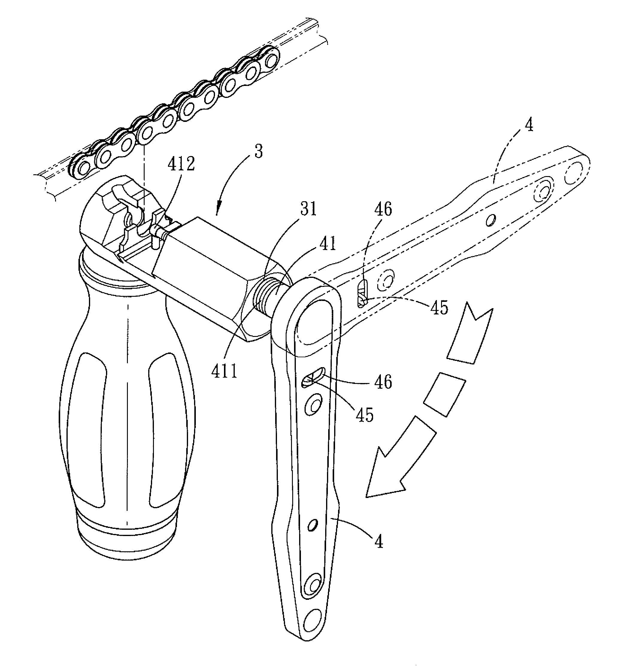
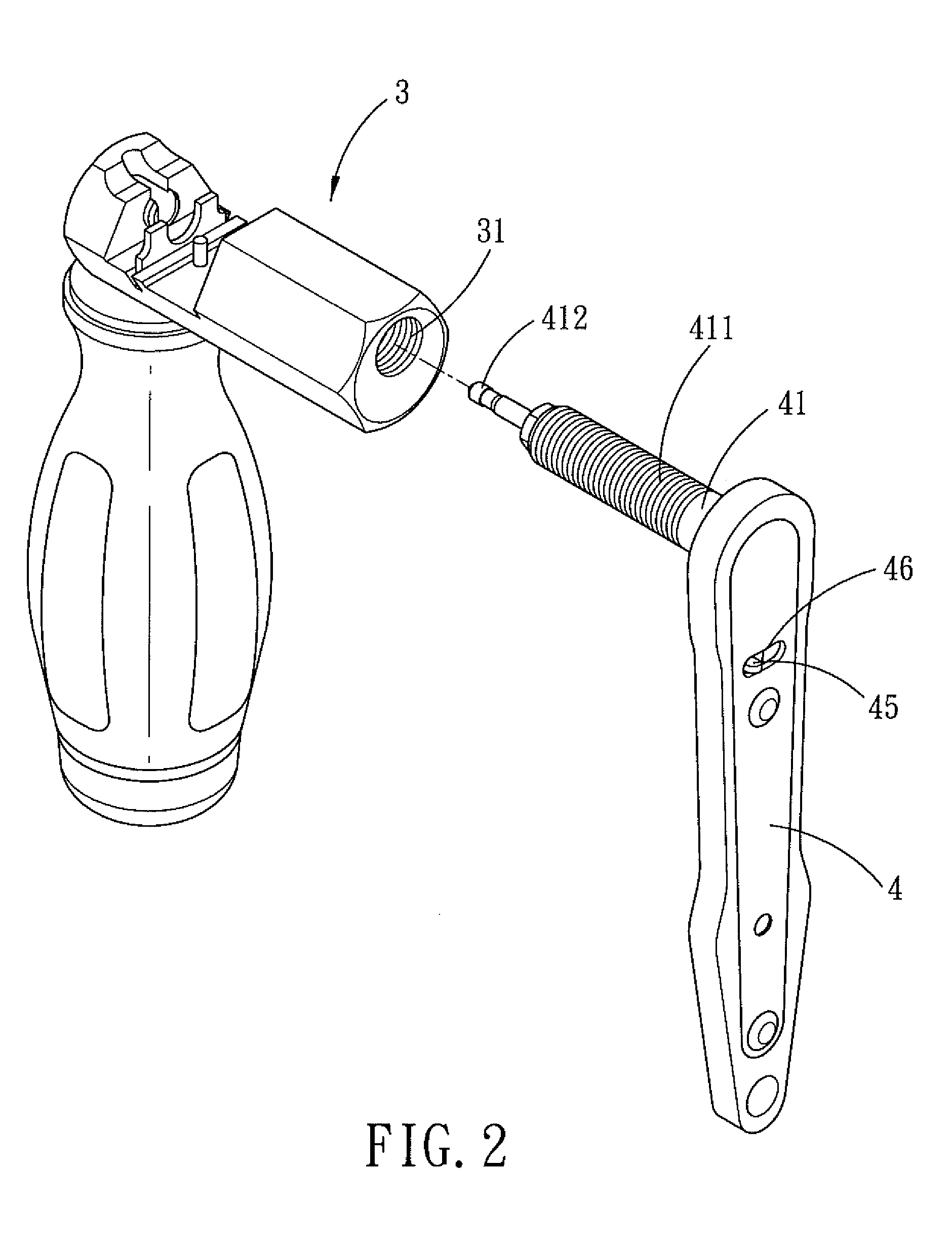
[0015]Referring to FIGS. 2-4, a ratchet arrangement for a chain splitter for disconnecting a chain link in accordance with a preferred embodiment of the present invention is shown and comprises a splitter body 3 and a ratchet wrench 4.

[0016]The splitter body 3 is formed with a threaded hole 31.

[0017]The ratchet wrench 4 is integrally formed on a ratchet wheel 42 of the ratchet wrench 4, and a plurality of threads 411 is formed in the outer surface of the rotating rod 41 for enabling the rotating rod 41 to be screwed in the threaded hole 31 of the splitter body 3. The rotating rod 41 has one end integral with the body of the ratchet wrench 4, and the other end of the rotating rod 41 is a free end 412. By turning the ratchet wrench 4 within 90 deg...


PUM

PropertyMeasurementUnit
angleaaaaaaaaaa
displacementaaaaaaaaaa
sizeaaaaaaaaaa

Abstract

A ratchet arrangement of a chain splitter comprises a rotating rod integrally formed at a side of the ratchet wrench, and the rotating rod is to be screwed in a threaded hole of a splitter body. The ratchet wrench can reduce the required revolving space and the whole packing of the chain splitter, thus saving the required space when transporting the packed chain splitter.

Description

BACKGROUND OF THE INVENTION[0001]1. Field of the Invention[0002]The present invention relates to a ratchet arrangement for a chain splitter that is adapted for disconnecting a chain of a bicycle.[0003]2. Description of the Prior Art[0004]Please refer to FIG. 1, a conventional chain splitter for a bicycle chain is shown and comprises a rotating rod 11 installed at a side of a splitter body 1, and a rotating bar 12 is integrally formed with the rotating rod 11 and located at an end thereof, such that the rotating rod 11 and the rotating bar 12 form a T-shaped structure 13. In use, the user has to turn the rotating bar 12 360 degrees in order to push the rotating rod 11 to move, and then the displacement of the rotating rod 11 causes the positioning pin to move out of the bicycle chain. However, this conventional chain splitter still has the following disadvantages:[0005]The rotating bar 12 of the splitter body 1 must be rotated continuously over 360 degrees, then the positioning pin c...

Claims


Application Information

Patent Timeline
Patent Type & Authority Patents(United States)
IPC IPC(8): B25B13/00B21L21/00
CPCB21L21/00B25B27/22Y10T29/5377
Inventor HUANG, HONG-JHEN
Owner HUANG HONG JHEN
Why Eureka
Try Eureka