Disk drive estimating angular position of spindle motor during spin-up by computing differences in winding current rise times
a technology of winding current rise and angular position, which is applied in the direction of motor/generator/converter stopper, dynamo-electric converter control, instruments, etc., can solve the problems of increasing the overall spin-up time, reducing the performance of the spin-up operation, and not providing a reliable estimate of the back emf voltage generated by the spindle motor
- Summary
- Abstract
- Description
- Claims
- Application Information
AI Technical Summary
Benefits of technology
Problems solved by technology
Method used
Image
Examples
Embodiment Construction
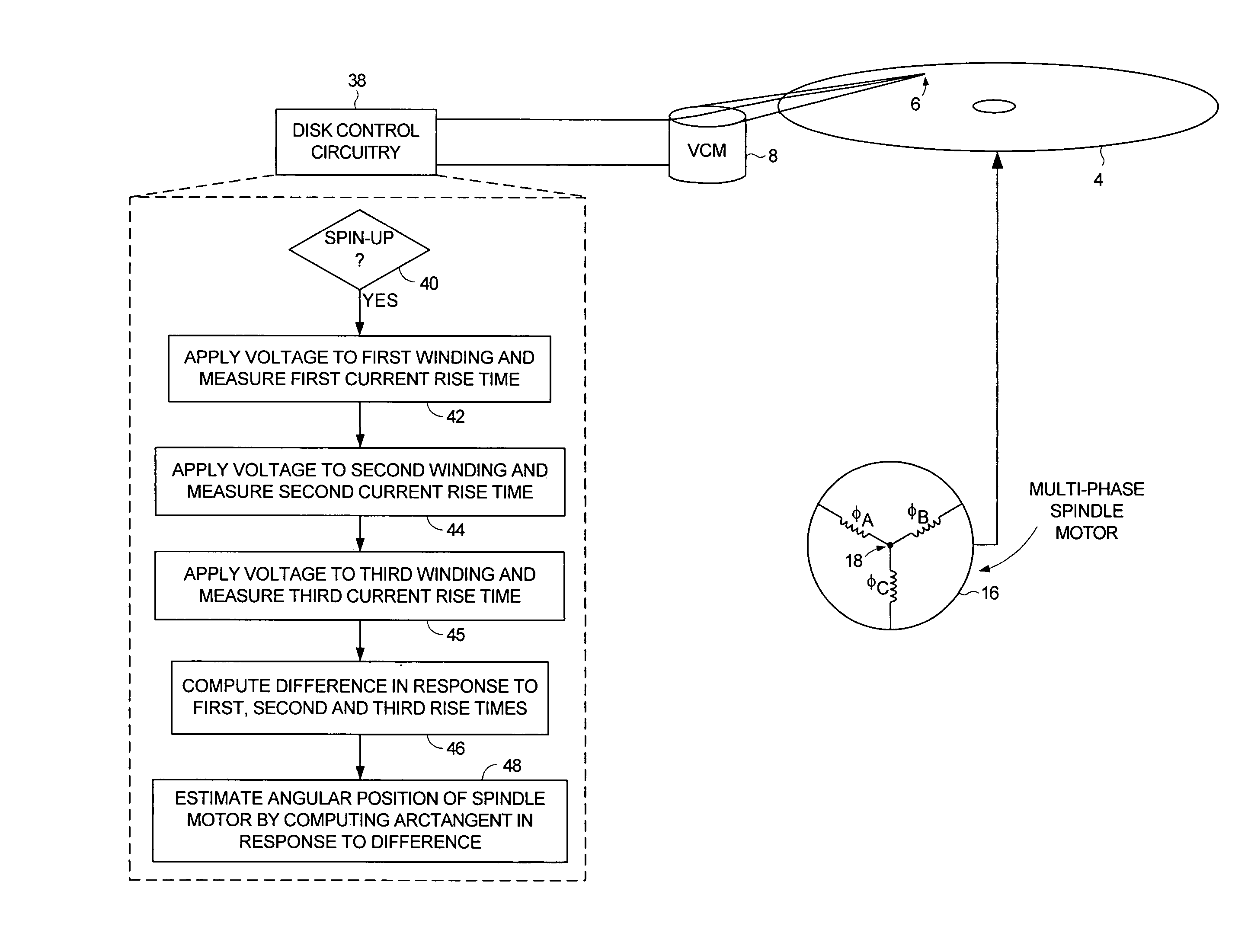
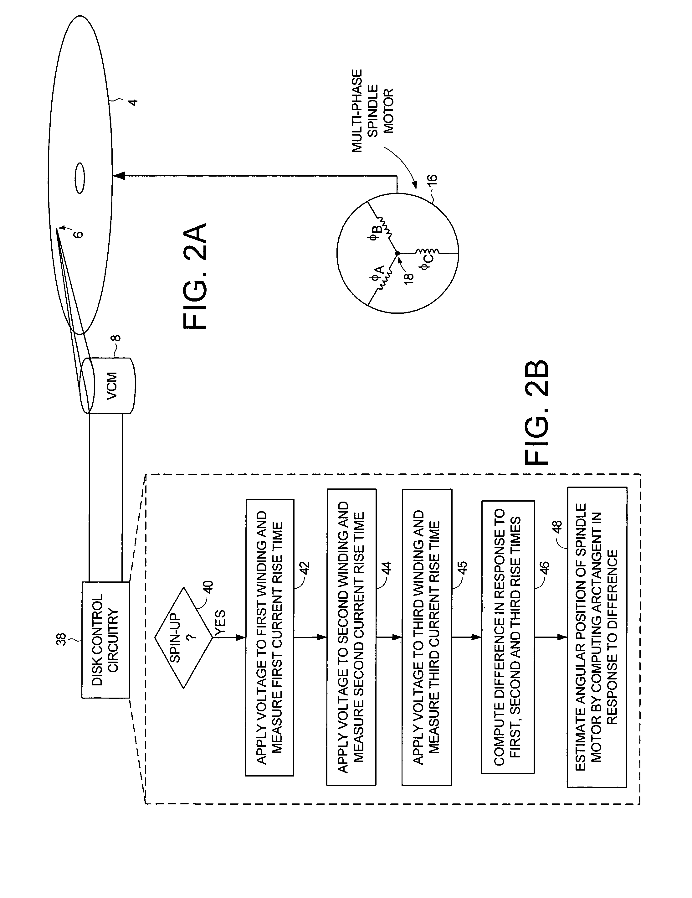
[0029]FIG. 2A shows a disk drive according to an embodiment of the present invention comprising a disk 4, a head 6 actuated over the disk 4, a spindle motor 16 for rotating the disk 4. The spindle motor 16 comprising a plurality of windings including at least a first winding, a second winding, and a third winding (in the embodiment of FIG. 2A, the spindle motor 16 comprises three coils φA, φB, and φC one of which represents a winding or two connected in series represents a winding). The disk drive further comprises disk control circuitry 38 for executing a spin-up operation of the spindle motor 16 as shown in the flow diagram of FIG. 2B. If at step 40 a spin-up operation is initiated, at step 42 a voltage is applied to the first winding and a first rise time is measured for current flowing through the first winding to reach a predetermined threshold. At step 44 a voltage is applied to the second winding and a second rise time is measured for current flowing through the second windin...
PUM
 Abstract
Description
Claims
Application Information
 - R&D
- Intellectual Property
- Life Sciences
- Materials
- Tech Scout
- Unparalleled Data Quality
- Higher Quality Content
- 60% Fewer Hallucinations
Browse by: Latest US Patents, China's latest patents, Technical Efficacy Thesaurus, Application Domain, Technology Topic, Popular Technical Reports.
© 2025 PatSnap. All rights reserved.Legal|Privacy policy|Modern Slavery Act Transparency Statement|Sitemap|About US| Contact US: help@patsnap.com


