Body fluid measuring adapter and body fluid measuring unit
a technology of which is applied in the field of body fluid measuring adapter and body fluid measuring unit, can solve the problems of blood being dried to deteriorate measurement accuracy, difficult to know exactly where the puncture needle protrudes, and the position of the puncture needle cannot be fine adjusted
- Summary
- Abstract
- Description
- Claims
- Application Information
AI Technical Summary
Problems solved by technology
Method used
Image
Examples
embodiment 1
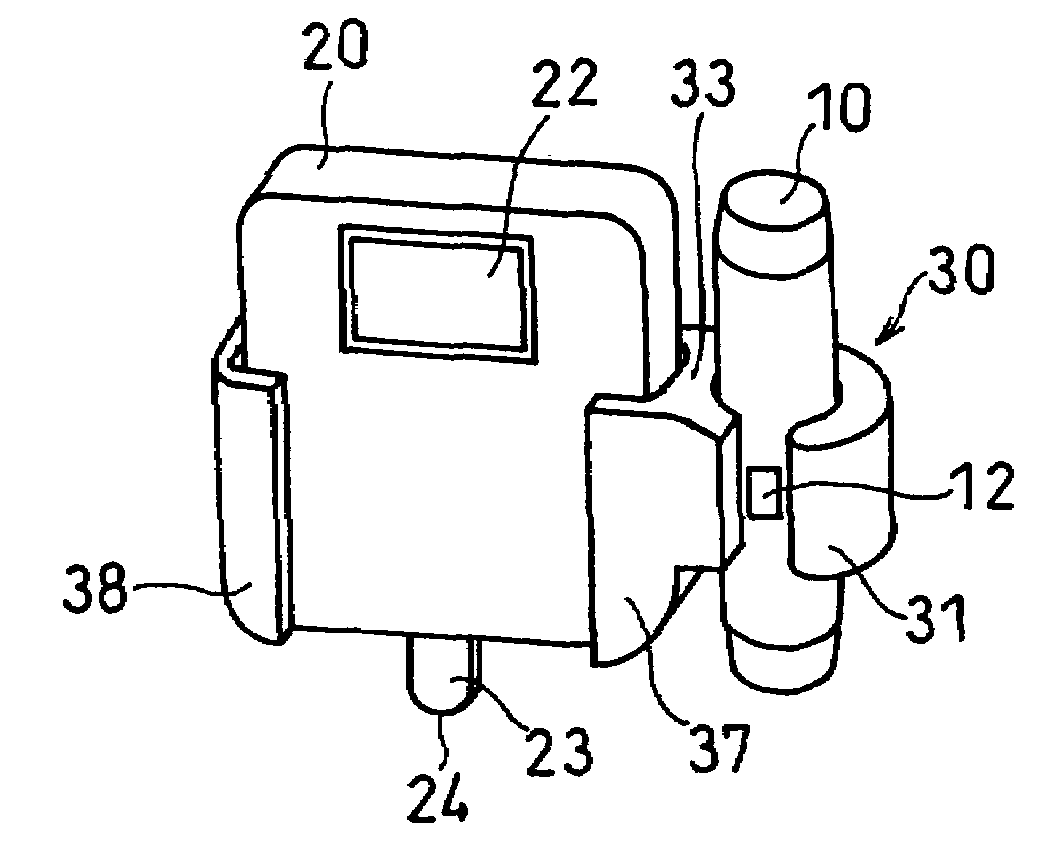
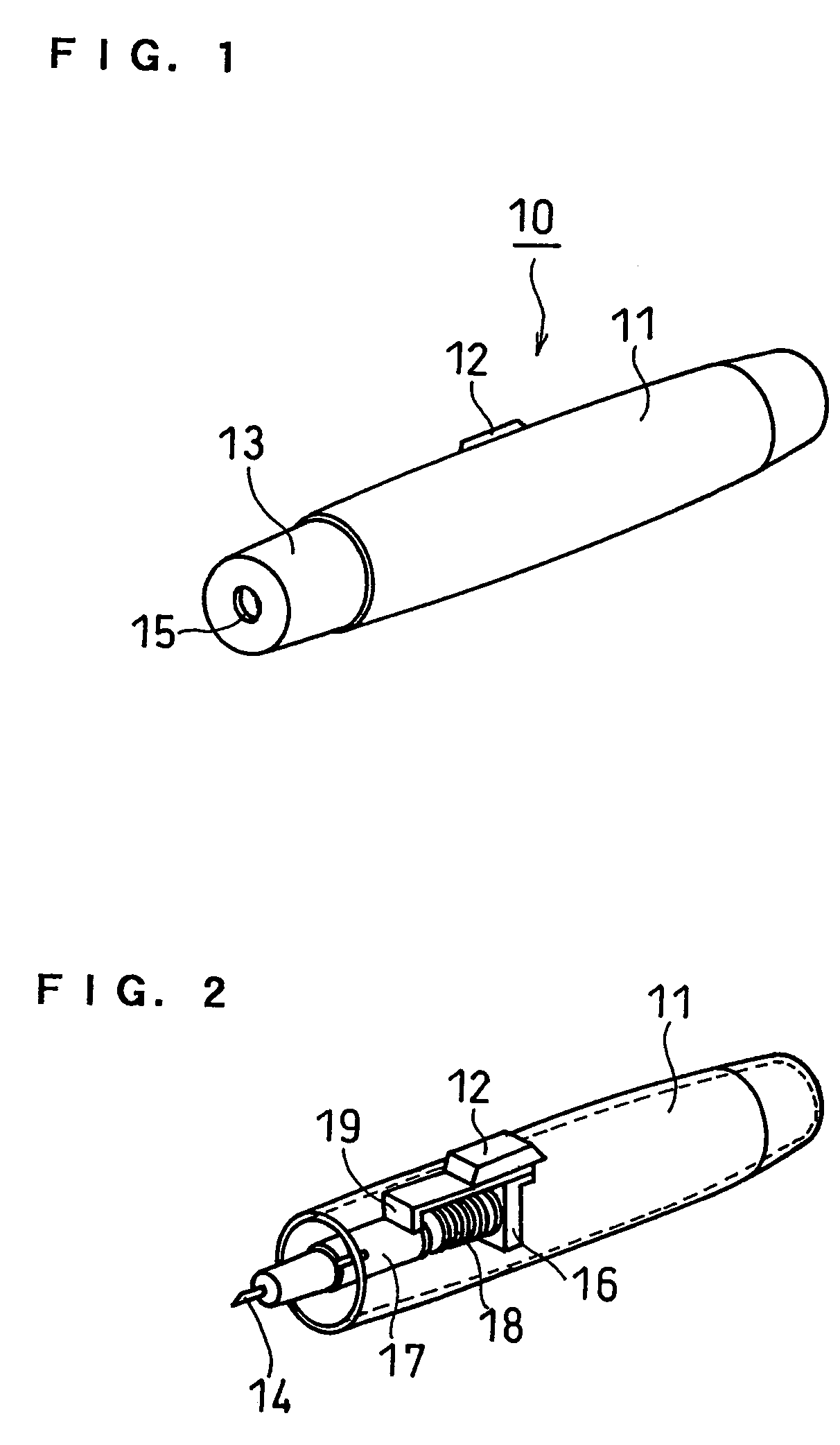
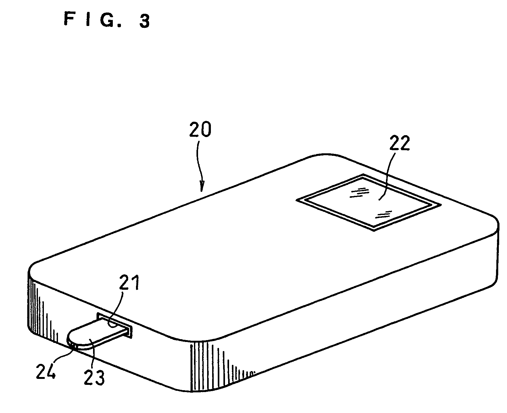
[0036]FIGS. 4 and 5 show an adaptor for body fluid measurement according to this embodiment. FIG. 6 shows a state where a puncture instrument and a measuring instrument are attached thereto. A puncture instrument 10 used herein includes, as shown in FIGS. 1 and 2, a cylindrical case 11 in which a puncture needle 14 is included, a cover 13 detachably connected to the tip of the case 11 and an operation button 12 projected outside the case 11. In the case 11, there are a needle holder 17 which is mounted on a base 16 and forwardly biased by a spring 18 and a stopper 19 which stops the needle holder 17 by engagement therewith. When the engagement between the stopper 19 and the needle holder 17 is released by operating the button 12, the puncture needle 14 protrudes forward through an aperture 15 in the cover 13 on the tip of the case 11. In loading the puncture needle 14 into the needle holder 17, the cover 13 is detached.
[0037]By the puncture needle 14 protruded from the case 11, part...
embodiment 2
[0049]FIG. 8 shows an adaptor for measurement 40 according to Embodiment 2.
[0050]The adaptor for measurement 40 includes a cylindrical puncture instrument holding section 41 having a slit 45, a measuring instrument holding section 42 having embrace lugs 47 and 48 and a lug 43 connecting the both. The adaptor is designed such that an axis Y of a hollow part 46 of the puncture instrument holding section 41 and an axis X of a hollow part 49 of the measuring instrument holding section 42 intersect with each other below the adaptor 40. FIG. 9 shows a state where a puncture instrument 10 and a measuring instrument 20 same as those of Embodiment 1 are attached to the adaptor 40.
[0051]The adaptor 40 of this embodiment is different from the adaptor for measurement 30 of Embodiment 1 in the following points.
[0052]1) The puncture instrument holding section 41 is arranged on the back of the measuring instrument holding section 42.
[0053]2) The puncture instrument holding section 41 is arranged s...
embodiment 3
[0055]FIG. 10 shows an adaptor 50 according to this embodiment.
[0056]The adaptor 50 is made of an elastic synthetic resin as is the case of Embodiment 1. A puncture instrument holding section 61 and a measuring instrument holding section 52 are formed separately, but they are joined in use as described below. The puncture instrument holding section 61 is made of a cylinder having a slit 65 and includes a pair of joint lugs 64 formed on the side surface. Each of the lugs 64 has a projection 67 bended outwardly at the tip thereof. On the other hand, the measuring instrument holding section 52 has embrace lugs 57 and 58 for embracing the side surface of the measuring instrument. A partition 53 extending to the embrace lug 57 has a pair of joint lugs 51 formed on the side surface. On the surfaces of the lugs 51 opposing to each other, three pairs of convex portions 54a, 54b and 54c are arranged. These convex portions are angled differently with respect to the partition 53, i.e., to the ...
PUM
 Abstract
Description
Claims
Application Information
 - R&D
- Intellectual Property
- Life Sciences
- Materials
- Tech Scout
- Unparalleled Data Quality
- Higher Quality Content
- 60% Fewer Hallucinations
Browse by: Latest US Patents, China's latest patents, Technical Efficacy Thesaurus, Application Domain, Technology Topic, Popular Technical Reports.
© 2025 PatSnap. All rights reserved.Legal|Privacy policy|Modern Slavery Act Transparency Statement|Sitemap|About US| Contact US: help@patsnap.com


