
Devices and methods for controlling relative movement between layers of an electronic device

a technology of electronic devices and layers, applied in the direction of electric apparatus casings/cabinets/drawers, instruments, non-rotary current collectors, etc., can solve the problems of operating problems within the electronic device, and each service or function typically has an established

Inactive Publication Date: 2007-08-07
QUALCOMM INC
View PDF8 Cites 40 Cited by
  • Summary
  • Abstract
  • Description
  • Claims
  • Application Information

AI Technical Summary

Benefits of technology

The patent text describes a system and method for controlling the movement of layers in an electronic device. This allows for the exposure of different functional components on the device while preventing others from being exposed simultaneously. The system includes a limiting member that can be moved into different positions to prevent movement in a certain direction. The technical effect of this invention is to provide a more efficient and effective way to control the movement and actuation of electronic devices.

Problems solved by technology

As such, having separate devices perform each service or function creates a problem for a user who requires more than one or two services / functions offered by these portable devices.
One drawback of incorporating many operational modes into a single device, however, is that each service or function typically has an established configuration, including the overall shape and the number and specific types of components.
One issue with such portable devices having multiple layers of functional components is that it may be possible to actuate more than one layer at one time.
The resulting actuation of more than one operational mode may cause confusion for the user, and may create operational problems within the electronic device.

Method used


Image

  • Devices and methods for controlling relative movement between layers of an electronic device
  • Devices and methods for controlling relative movement between layers of an electronic device
  • Devices and methods for controlling relative movement between layers of an electronic device

Examples


Embodiment Construction

[0040]The disclosed embodiments include devices and methods for controlling relative movement between layers of an electronic device.

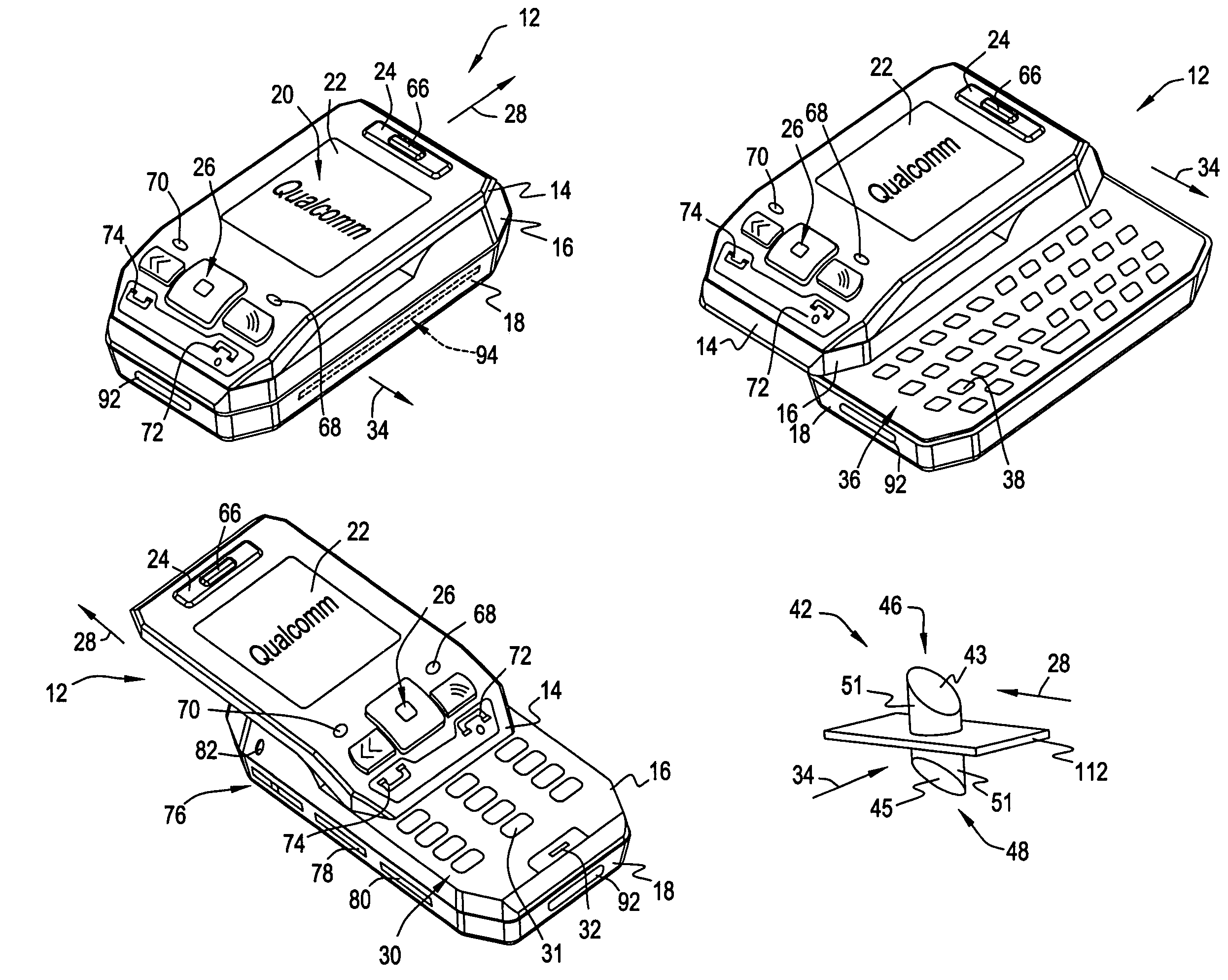
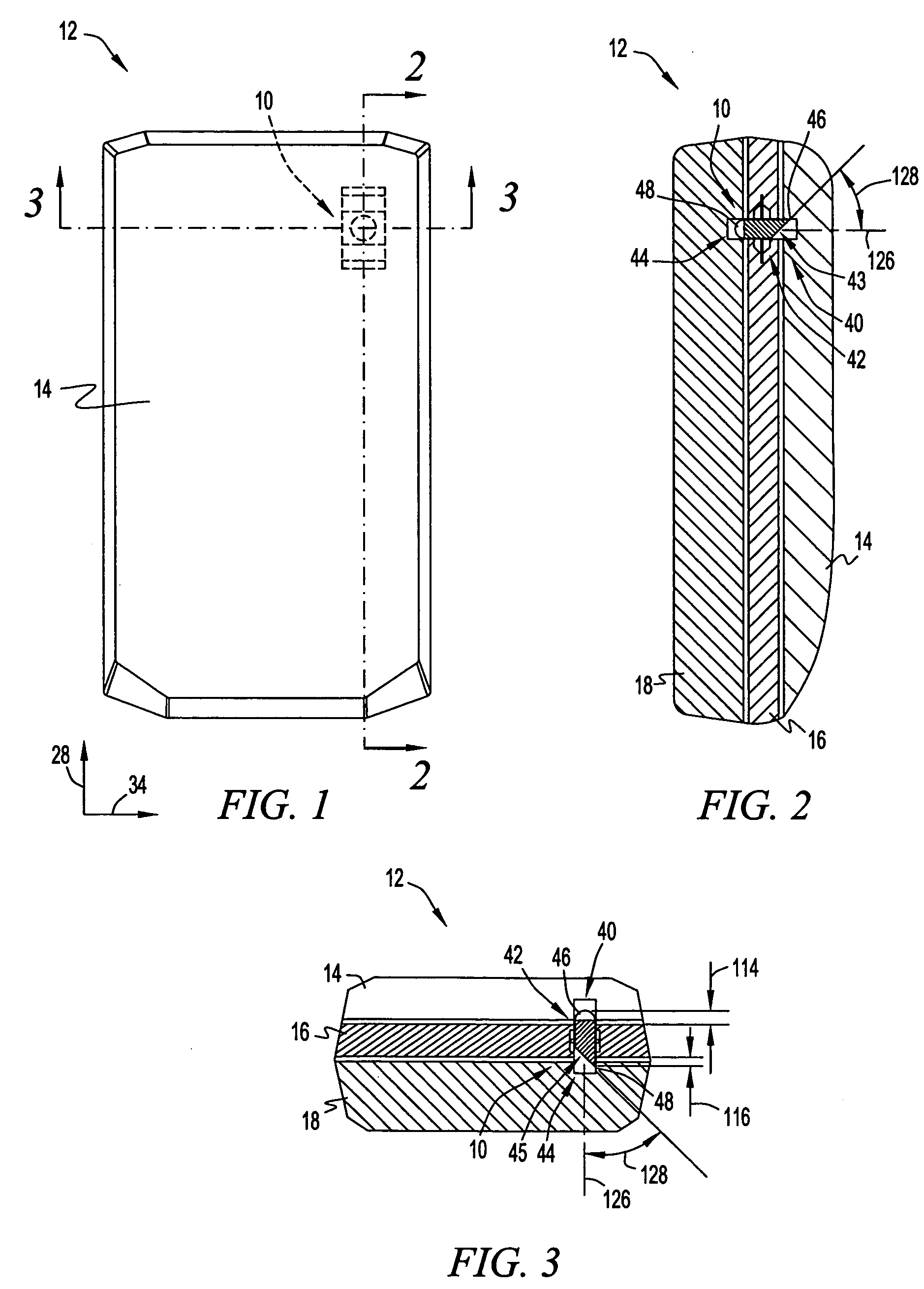
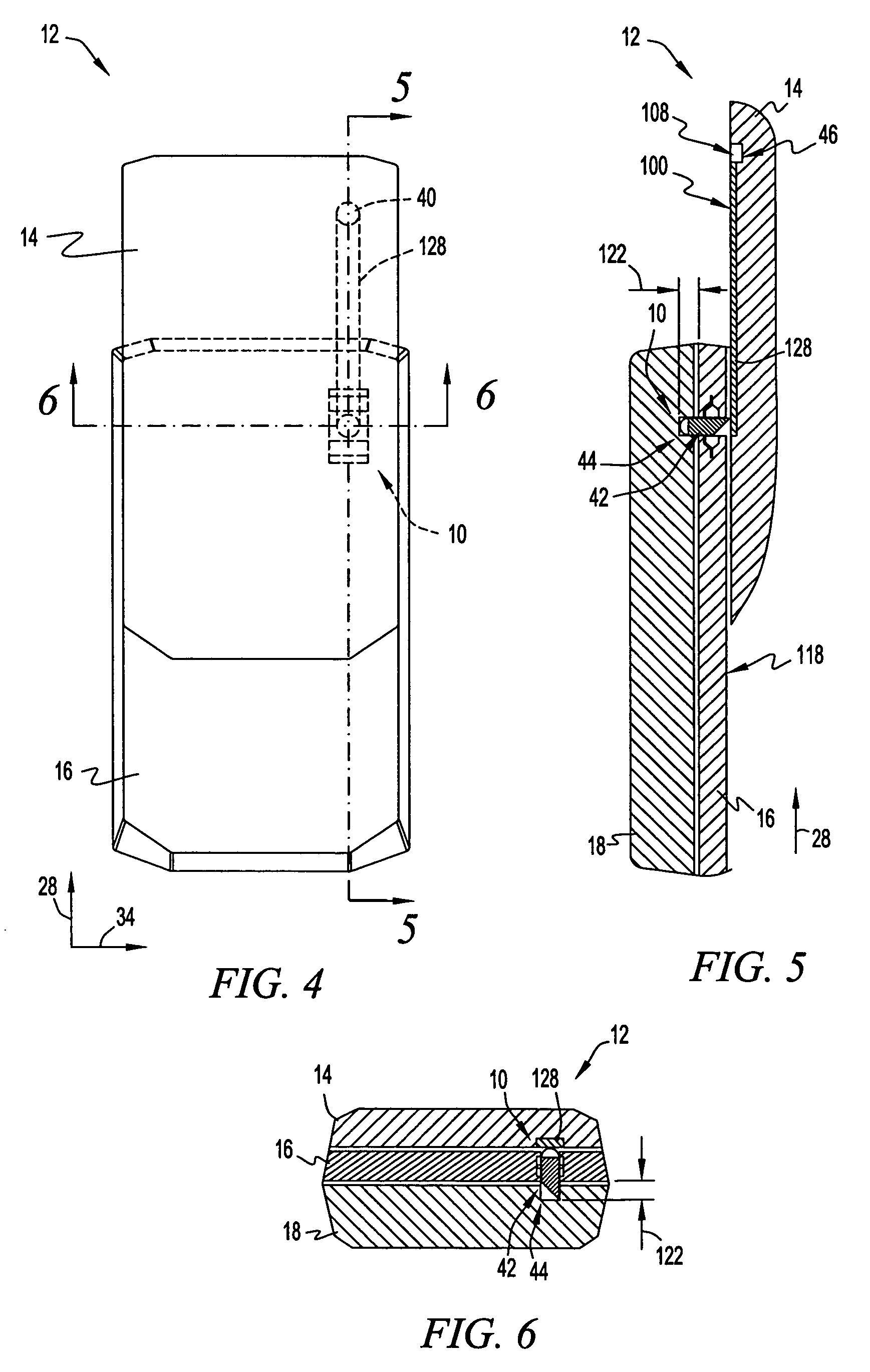
[0041]Referring to FIGS. 1-12, in one embodiment, a layer locking system 10 (FIGS. 1-9) controls relative movement of portions of electronic device 12, which has a number of movably interconnected module layers 14, 16, 18 that provide electronic device 12 with a number of functional capabilities. In one embodiment, for example referring to FIGS. 1-3 and 10, electronic device 12 may have a first operational mode, such as a gaming mode, when module layers 14, 16, 18 are positioned in a first or neutral position where a first set of components 20 (FIG. 10) such as a display unit 22 and directional keypads 24, 26 on the exterior of electronic device 12 may be utilized. Referring to FIGS. 4-6 and 11, electronic device 12 may have a second operational mode, such as a phone or audio communications mode, when first module layer 14 is moved in a first direction...


PUM


Abstract

The disclosed embodiments provide devices and methods for movably connecting module layers of an electronic device to actuate one operational mode while limiting actuation of other modes. In one embodiment, an electronic device includes a first module layer movable in a first direction and a second module layer movably connected relative to the first module layer. Further, a third module layer is movably connected relative to the second module layer and movable in a second direction. Additionally, a limiting member is movably positioned relative to the module layers to be engageable with the third module layer to prevent movement in the second direction during movement of the first module layer in the first direction, or to be engageable with the first module layer to prevent movement in the first direction during movement of the third module layer in the second direction.

Description

CROSS-REFERENCE TO RELATED APPLICATIONS[0001]This application is related to the following U.S. patent applications, each assigned to the present assignee and each hereby incorporated by reference:[0002]Application Ser. No. 10 / 718,125, entitled “A Portable Device With Versatile Keyboard,” filed Nov. 19, 2003; and[0003]Application Ser. No. 10 / 945,576, filed concurrently herewith, entitled “Devices And Methods For Controlling Relative Movement Between Layers Of An Electronic Device.”BACKGROUND[0004]The disclosed embodiments relate to portable electronic devices, and more particularly, to devices and methods for controlling relative movement between layers of an electronic device.[0005]Portable electronic devices such as mobile phones, pagers, handheld computers, personal digital assistants (“PDA's”) and hand-held gaming devices are becoming increasingly popular for both business and personal use. One advantage of these devices is their portability due to their small size, light weight,...

Claims


Application Information

Patent Timeline
Patent Type & Authority Patents(United States)
IPC IPC(8): H01R39/00G06F1/16H04B1/38
CPCG06F1/1624G06F1/1671G06F1/1679H04M1/0239H04M1/0247G06F2200/1614H04B1/38
Inventor SANTOS, THEODORE R.LEJMAN, ANDREW G.LARSON, DAVIDSWANSON, JEFFREY
Owner QUALCOMM INC
Learn More