
Lumbar with flexwires in cross

a technology of flexwires and lumbar supports, applied in the direction of chairs, vehicle components, vehicle arrangements, etc., can solve the problems of increased muscle activation, lower back pain, increased ligament tension, etc., and achieve the effect of eliminating the “punctual effect”

Inactive Publication Date: 2007-08-07
L & P PROPERTY MANAGEMENT CO
View PDF20 Cites 16 Cited by
  • Summary
  • Abstract
  • Description
  • Claims
  • Application Information

AI Technical Summary

Benefits of technology

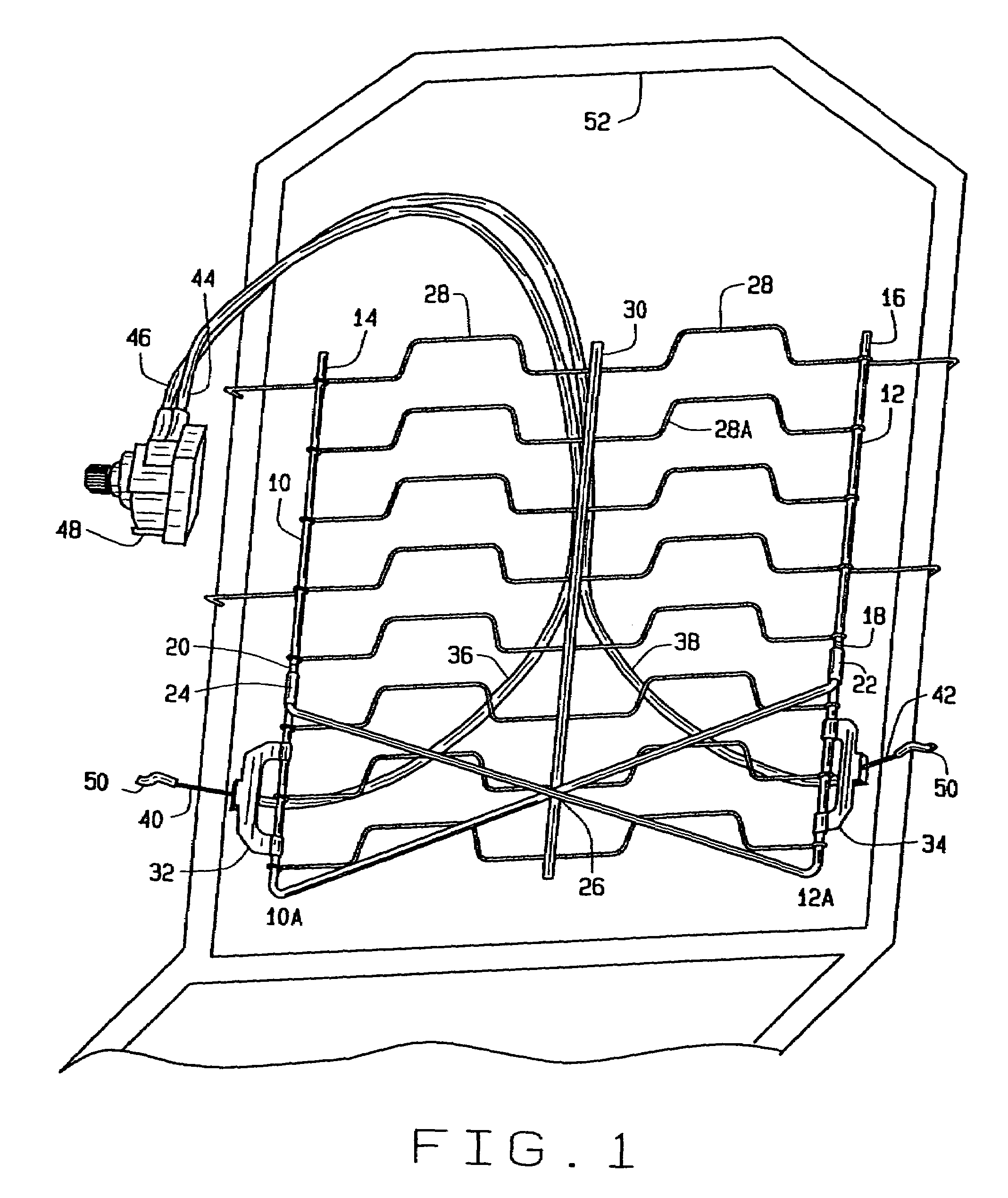
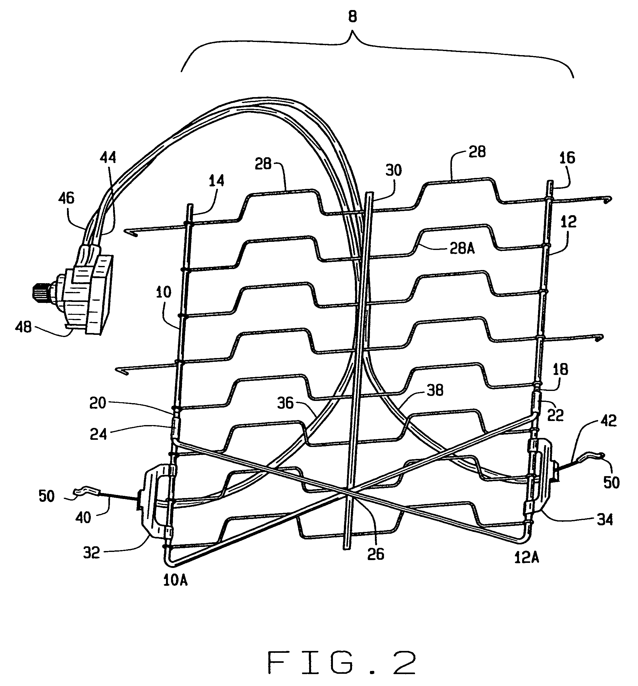
[0009]One aspect of the present invention relates to a lumbar support device having a pair of side rails, a plurality of transverse wires extending between the side rails, a pair of cross bars extending between the side rails, a seat frame, and an actuator assembly which operatively connects to the side rails and seat frame to change the curvature of the lumbar support device. It is the main object of this present invention to provide cross-bars in the lumbar region to create stiffer lumbar support without creating a “hole” effect just above the lumbar region. The present invention is also designed with cross-bars to eliminate the “punctual effect” that occurs with lumbar support devices.
[0010]Another aspect of the present invention pertains to the lumbar support device comprising cross-bars that may be connected at varying points on the side rails to adjust the apex height. The present invention may also be designed with cross-bars having greater average bending stiffness than the transverse wires. This increased average bending stiffness provides increased stiffness in the lumbar region.
[0013]In another aspect of the present invention, the support device may be designed with bends in the transverse wires. These bends create an increased suspension effect which increases comfort.
[0014]It is the purpose of the present invention to provide a lumbar support device that is simple and affordable to manufacture. The present invention may be manufactured from a normal outline by increasing the length of the side rails. The side rails may be pre-bended near their ends in one of the first steps of the outline. Then, the side rails may be bended in a shepherd hook formation and clipped together on the opposite side rail.
[0015]It is a further purpose of the present invention to provide a lumbar support device with increased durability.
[0016]It is a further purpose of the present invention to provide a mechanically simplified lumbar support device that provides the appropriate stiffness in the lumbar region without creating a “hole” effect.

Problems solved by technology

Incorrect seating posture can lead to lower back pain, increased muscle activation, increased tension on ligaments, and increased pressure on the spine.
Moreover, lack of lumbar support causes discomfort to the individual in the seated position.
Particularly in a car seat, the problems that stem form incorrect seating posture, i.e. lower back pain and uncomfortability, may lead to reduced concentration and reduced driving safety.
The known lumbar support devices do not effectively support the lumbar region.
Some of these lumbar supports are ineffective because the whole seat moves forward instead of just the lumbar region.
This does not effectively support the lumbar region.
Further, other lumbar supports that move independently of the seat do not provide the effective support.
Moreover, these support systems are not stiff or durable.
However, baskets often result in a punctual effect.
Moreover, some of the supports with baskets create an aggressive situation which is not comfortable to the individual.
These baskets are also more expensive to manufacture than lumbar supports without baskets because they require more material and labor.
However, many prior art devices continue to produce the hole effect above the stiffer lumbar area.

Method used


Image

  • Lumbar with flexwires in cross
  • Lumbar with flexwires in cross
  • Lumbar with flexwires in cross

Examples


Embodiment Construction

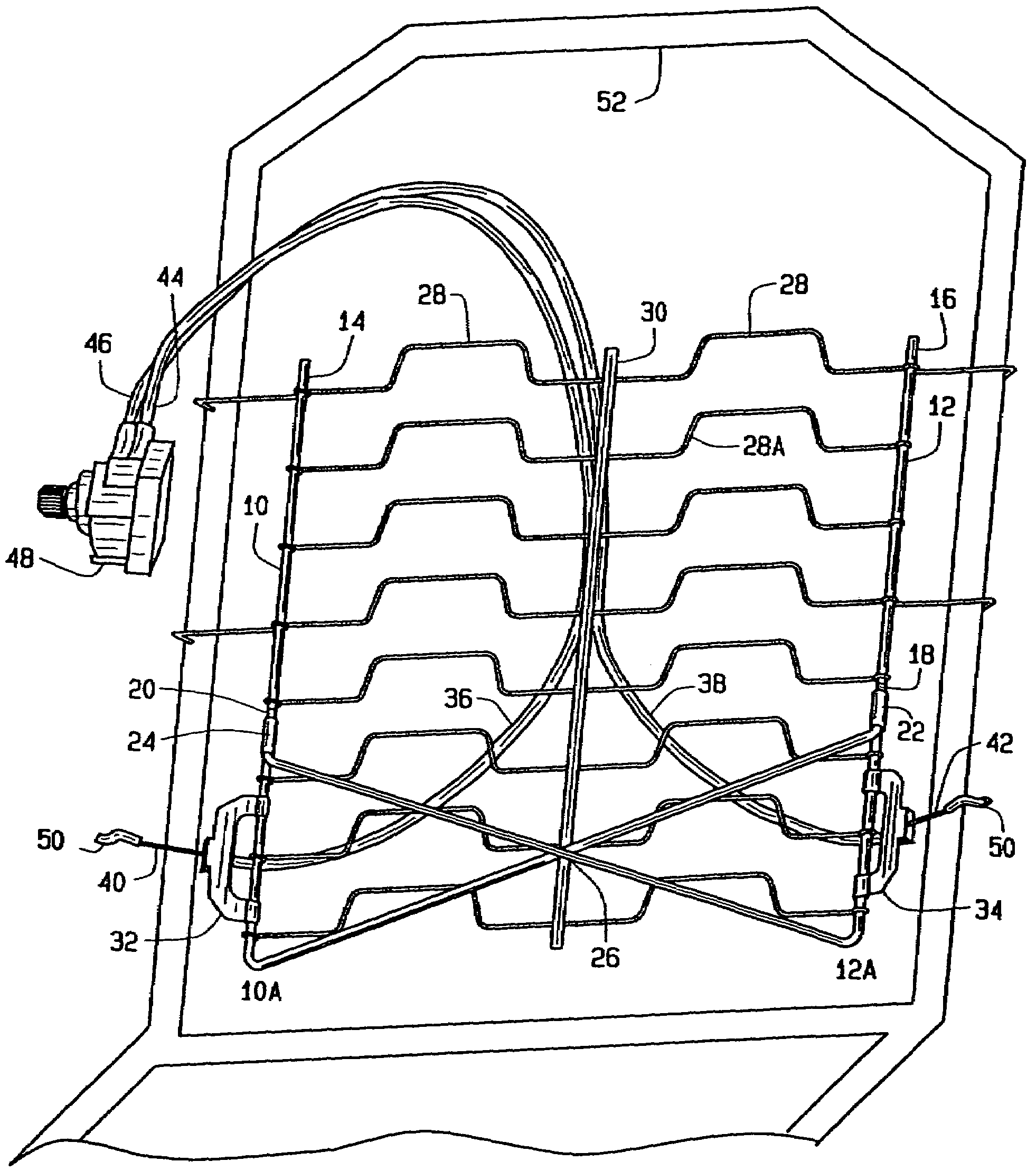
[0022]As shown in FIGS. 1-3, the preferred embodiment of the lumbar support device (8) for a seat back of a vehicle includes a pair of side rails (10 and 12) having first ends (14 and 16) and second ends (18 and 20). The side rails (10 and 12) are comprised of paper wrapped or plastic coated steel wire. Side rail (10) is angled at (10A) and the second end (18) of side rail (10) is attached to side rail (12). Side rail (12) is angled at (12A) and the second end (20) of side rail (12) is attached to side rail (10). These attachments are made by clips (22 and 24). These connections form a cross or X-shape (26). The side rails may incorporate bends (26A) in the cross as shown in FIG. 3. A plurality of transverse supporting wires (28) are provided between the side rails (10 and 12). These transverse supporting wires (28) are wound around the side rails (10 and 12) to fixedly attach. However, the transverse supporting wires may be fixedly attached to the side rails by other means known in...


PUM


Abstract

This invention is a lumbar support device with a pair of side rails, a plurality of transverse wires and a pair of cross-bars extending between the pair of side rails. The lumbar support device is designed for a seat back of a vehicle seat to support an occupant's lumbar region. The invention is designed to include an actuator assembly for changing the contour of the lumbar support device.

Description

CROSS-REFERENCE TO RELATED APPLICATIONS[0001]None.STATEMENT REGARDING FEDERALLY SPONSORED RESEARCH OR DEVELOPMENT[0002]Not Applicable.APPENDIX[0003]Not Applicable.BACKGROUND OF THE INVENTION[0004]1. Field of the Invention[0005]The present invention relates generally to lumbar support devices. More particularly, the present invention is a lumbar support device in the seat back of a vehicle seat for supporting an occupant's lumbar region. The present invention involves a lumbar support device comprising a wire framework having two side rails adapted to be suspended in a seat frame and between which extend a plurality of transverse wires. The present invention is designed with cross-bars to create a stiffer lumbar feeling without creating a “hole” effect just above the lumbar region.[0006]2. Related Art[0007]Lumbar support systems are important for assisting an individual in achieving an anatomically correct seating posture. Incorrect seating posture can lead to lower back pain, increa...

Claims


Application Information

Patent Timeline
Patent Type & Authority Patents(United States)
IPC IPC(8): A47C7/46
CPCB60N2/66B60N2/6671
Inventor SAMAIN, MAXIME ARTHUR MAURICEVANPARYS, MAARTEN
Owner L & P PROPERTY MANAGEMENT CO
Learn More