
Apparatus diagnostic device and diagnosed device

Inactive Publication Date: 2007-07-31
MURATA MASCH LTD
View PDF31 Cites 8 Cited by
  • Summary
  • Abstract
  • Description
  • Claims
  • Application Information

AI Technical Summary

Benefits of technology

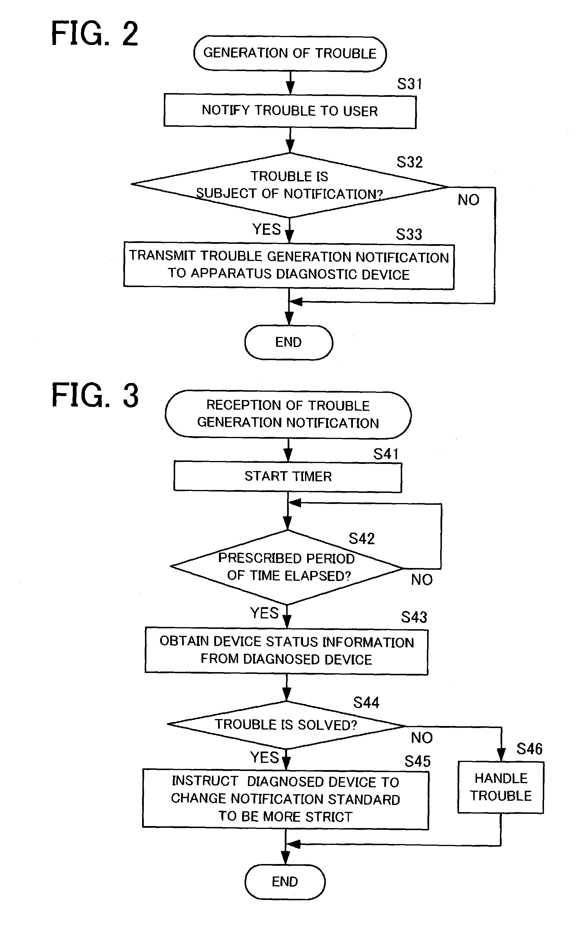
[0009]An apparatus diagnostic device of the present invention to be used in an apparatus diagnostic system includes a communication unit which communicates with a diagnosed device through a communication line. In addition, the apparatus diagnostic device includes a control unit which receives a problem generation notification from the diagnosed device via the communication unit, and which controls the diagnosed device to change a notification standard of the problem generation notification when necessary. For example, when a prescribed period of time elapses after receiving the problem generation notification, the control unit determines whether or not the problem has been solved in accordance with apparatus status information obtained from the diagnosed device. Alternatively, the control unit determines whether or not to solve the problem in accordance with a determination of whether or not a problem solved notification has been received from the diagnosed device within a prescribed period of time after receiving the problem generation notification. Especially when it is determined that the problem has been solved in accordance with the apparatus status information, an instruction can be sent to the diagnosed device to change the notification standard of the problem generation notification for more severe problems. Accordingly, for example, even when a problem is generated, if the user solves the problem within a prescribed period of time, this type of problem can be excluded from a subject of transmission of the problem generation notification for all notifications thereafter. Therefore, contact is not made with the service center or the maintenance worker does not have to make a visit for the problem which can be solved by the user. As a result, the user is not disturbed by unnecessary contacts or visits, and the maintenance costs can be reduced.
[0010]In addition, the diagnosed device of the present invention to be used in the apparatus diagnostic system includes a communication unit which communicates through a communication line, a storage unit which stores a notification standard which is a standard for determining whether or not to transmit a problem generation notification, and a control unit which changes the notification standard when necessary. When a problem is generated, the control unit references the notification standard stored in the storage unit. In case the notification standard is satisfied, the control unit transmits the problem generation notification to the apparatus d

Problems solved by technology

In addition, even for the same type of problem, if a long period of time has passed since the generation of the last problem, there are times when the user does not remember a method for solving the problem.
Furthermore, even for the same type of problem, there are times when the user in charge has ch

Method used


Image

  • Apparatus diagnostic device and diagnosed device
  • Apparatus diagnostic device and diagnosed device
  • Apparatus diagnostic device and diagnosed device

Examples


Example

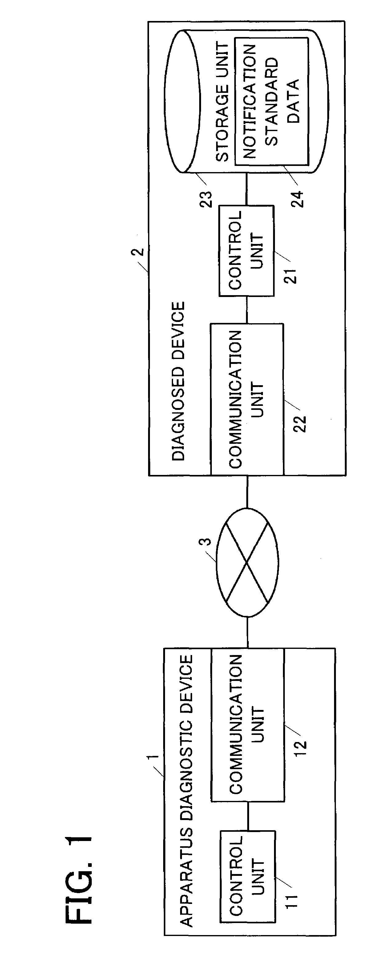
[0017]FIG. 1 is a block diagram showing an example of a system including a first embodiment of the present invention. In the drawing, reference number 1 is an apparatus diagnostic device, 2 is a diagnosed device, 3 is a network, 11 is a control unit, 12 is a communication unit, 21 is a control unit, 22 is a communication unit, 23 is a storage unit, and 24 is notification standard data.

[0018]The apparatus diagnostic device 1 (center terminal) receives a problem generation notification from one or a plurality of diagnosed device (user terminal) via the network 3. Then, the apparatus diagnostic device 1 diagnoses the problem in accordance with the content of the notification. In accordance with the diagnosed result, for example, the user of the diagnosed device can be contacted by telephone, or a maintenance worker can make a visit.

[0019]The apparatus diagnostic device 1 includes the control unit 11, the communication unit 12 or the like. The communication unit 12 communicates with the...

Example

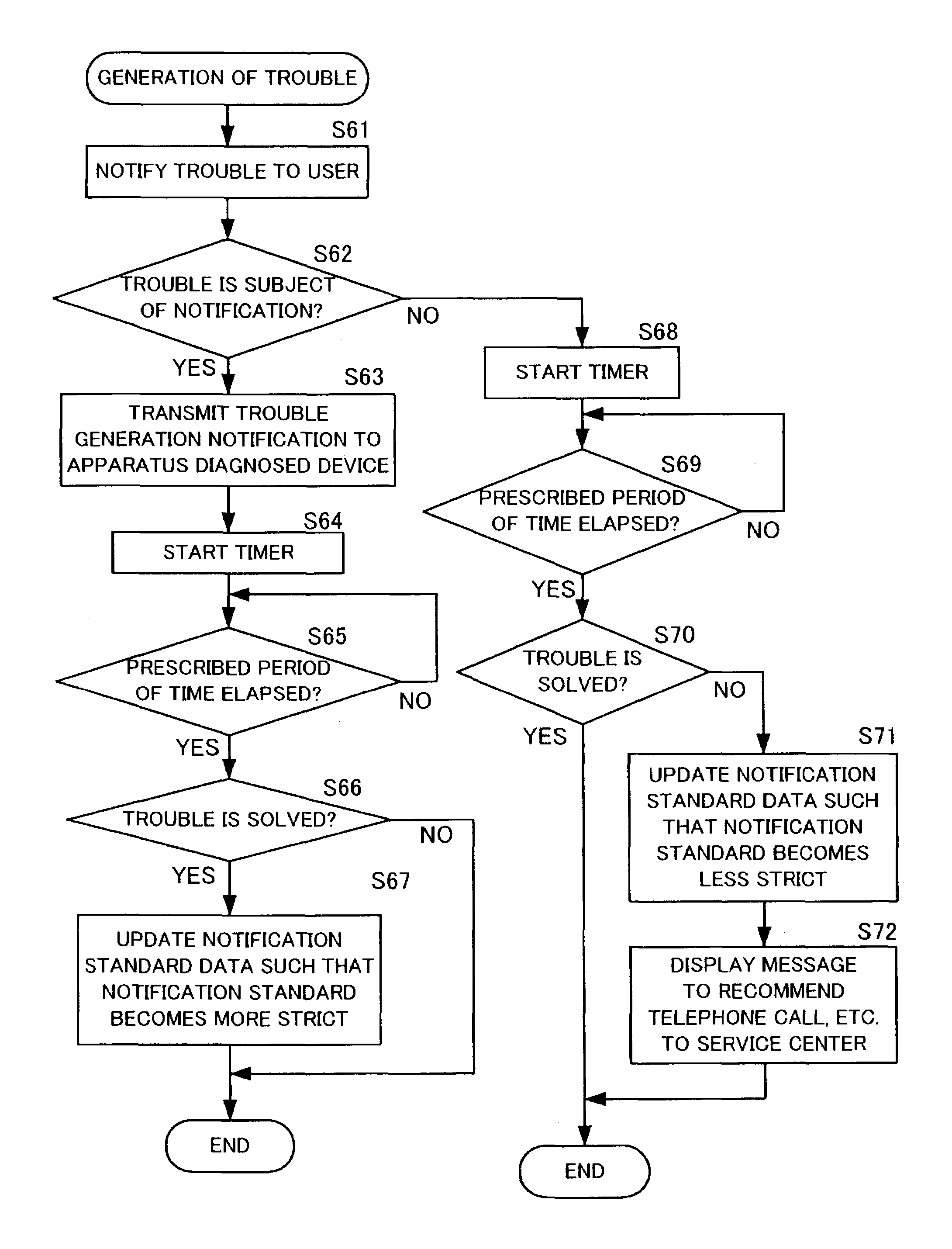
[0039]Next, an example of a system including a second embodiment of the present invention will be described. Further, a configuration of the system including the second embodiment of the present invention is the same as the configuration shown in FIG. 1. Therefore, the drawing showing the configuration of the system including the second embodiment will be abbreviated, and some of descriptions that overlap with the description for the first embodiment will be abbreviated. In the above-described first embodiment, the apparatus diagnostic device 1 instructs the diagnosed device to change the notification standard for the transmission of the problem generation notification. However, in the second embodiment, the diagnosed device 2 can change the notification standard without an instruction from the apparatus diagnostic device 1. Therefore, the apparatus diagnostic device 1 can have a configuration the same as the configuration of the conventional diagnostic device.

[0040]When detecting t...


PUM


Abstract

An apparatus diagnostic device includes a communication unit that communicates with a diagnosed device through a communication line, and a control unit that controls to receive a problem generation notification from the diagnosed device via the communication unit, to determine whether or not to solve a problem in accordance with apparatus status information obtained from the diagnosed device after an elapse of a prescribed period of time, and to have a notification standard of the problem generation notification changed by the diagnosed device when necessary.

Description

BACKGROUND OF THE INVENTION[0001]1. Field of the Invention[0002]The present invention relates to an apparatus diagnostic system which diagnoses a remote diagnosed device by transmitting a problem generation notification to an apparatus diagnostic device when a problem is generated in the diagnosed device.[0003]2. Description of the Related Art[0004]There is a conventional apparatus diagnostic system which detects problems such as a diagnosed device malfunctioning, and automatically sends a problem generation notification to an apparatus diagnostic device of a service center or the like via a communication line. The apparatus diagnostic device analyzes the problem generation notification transmitted from the diagnosed device. When necessary, contact is made with a user of the diagnosed device, or a maintenance worker makes a visit to repair the diagnosed device.[0005]In such a conventional apparatus diagnostic system, when detecting a prescribed problem, the diagnosed device uniforml...

Claims


Application Information

Patent Timeline
IPC IPC(8): G06F11/00G06Q50/10G06Q50/00H04L1/22H04L12/24H04L12/26
CPCH04L41/06H04L43/065H04L43/0817
Inventor OSHIMA, OSAMU
Owner MURATA MASCH LTD
Learn More