Eureka AIR delivers breakthrough ideas for toughest innovation challenges, trusted by R&D personnel around the world.

System and method for stochastic aircraft flight-path modeling

a flight path and stochastic aircraft technology, applied in simultaneous traffic control systems, navigation instruments, instruments, etc., can solve the problems of substantially obviating one or more of the disadvantages of related models, and achieve the effects of reducing proximity alerts, minimizing flight time, and reducing the risk of collision

Active Publication Date: 2007-07-24
MITRE SPORTS INT LTD
View PDF10 Cites 40 Cited by
  • Summary
  • Abstract
  • Description
  • Claims
  • Application Information

AI Technical Summary

Problems solved by technology

The use of these models substantially obviates one or more of the disadvantages of the related art.

Method used


Image

  • System and method for stochastic aircraft flight-path modeling
  • System and method for stochastic aircraft flight-path modeling
  • System and method for stochastic aircraft flight-path modeling

Examples


Embodiment Construction

[0027]Reference will now be made in detail to embodiments of the present invention, examples of which are illustrated in the accompanying drawings.

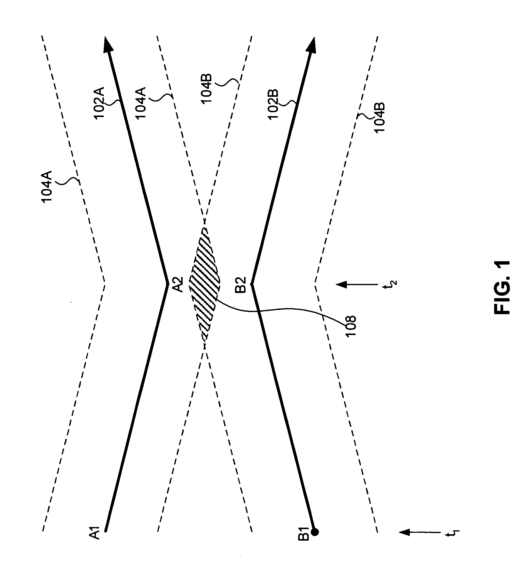
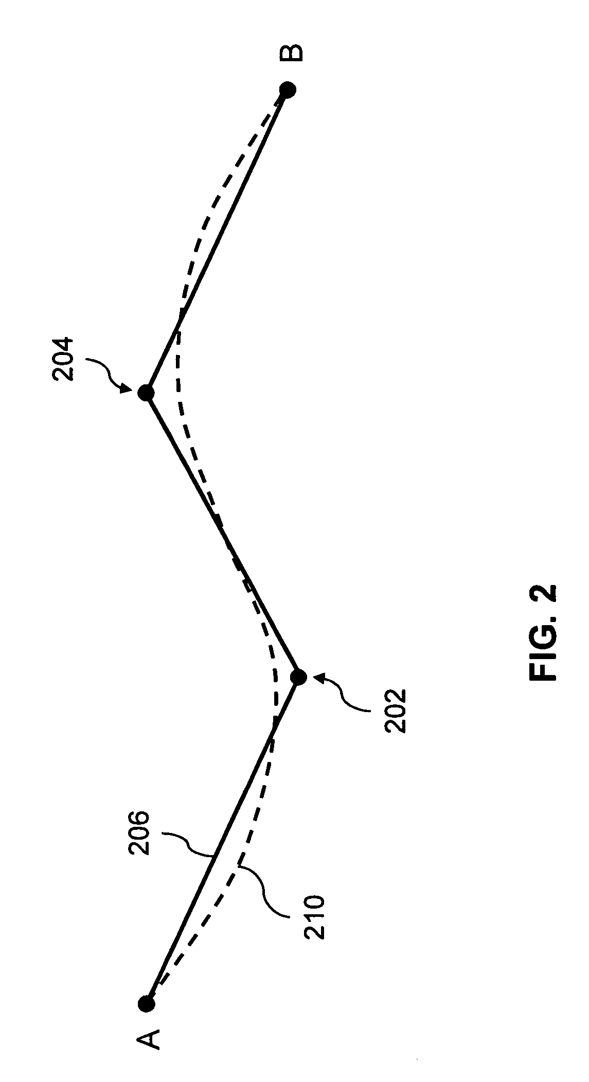
[0028]The present invention utilizes stochastic methods to model realistic variations in aircraft flight paths. These methods can be used to help evaluate decision support systems that are used in the air traffic control system, or, more generally, to produce air traffic scenarios composed of many simulated flights. The stochastic models assess how well different types of aircraft follow their planned routes. FIG. 9 shows a system-level diagram of how the present invention may be implemented in the form of computer algorithms to produce simulated flight paths. In one embodiment, simulated flight paths 940 are generated based on any or all of the waypoints 904, flight plans 906, static aircraft parameters 908, lateral models 910, longitudinal models 912, vertical models 914 and response time models 916, as described further below.

[0029]FIG...


PUM


Abstract

Stochastic models of aircraft flight paths and a method for deriving such models from recorded air traffic data. Each stochastic model involves identifying the flight plan for one or more aircraft; identifying important parameters from each flight plan, such as aircraft type, cruise altitude, and airspeed; optionally identifying flight plan amendments for each flight; representing each route of flight as a series of navigational fixes; representing at least one aircraft flight parameter probabilistically; modeling realistic differences in at least one dimension between each planned route of flight and the flight path as it might actually be flown; and communicating the modeled deviations or simulated flight paths to the user. At least one aircraft flight parameter is represented as a random variable with a particular statistical distribution, such as a normal (Gaussian), Laplacian, or logistic distribution; or with a more complex algorithm containing one or more random elements. The modeled flight parameters may be any of lateral position, longitudinal position, climb altitude, descent altitude, climb airspeed, descent airspeed, cruise airspeed, cruise altitude transition, or response time to a flight plan amendment.

Description

STATEMENT REGARDING FEDERALLY-SPONSORED RESEARCH AND DEVELOPMENT[0001]Statement under MPEP 310. The U.S. government has a paid-up license in this invention and the right in limited circumstances to require the patent owner to license others on reasonable terms as provided for by the terms of contracts Nos. DTFA01-93-C-00001 and DTFA01-01-C-00001, awarded by the Federal Aviation Administration.BACKGROUND OF THE INVENTION[0002]1. Field of the Invention[0003]The present invention relates to decision support tools for air traffic control (ATC) and to simulation and modeling of air traffic.[0004]2. Related Art[0005]In modern ATC systems, operational personnel use various decision support tools (DSTs) for aircraft route planning and for keeping aircraft safely separated as they move from origin to destination. Many of these tools include a trajectory modeling function to predict the future positions and altitudes of aircraft. Examples of such DSTs in the United States include the Collabor...

Claims


Application Information

Patent Timeline
Patent Type & Authority Patents(United States)
IPC IPC(8): G08G7/00G01S3/00
CPCG08G5/0039
Inventor LOVE, W. DWIGHTMCLAUGHLIN, MICHAEL P.LEJEUNE, ROLAND O.
Owner MITRE SPORTS INT LTD
Why Eureka
Eureka Blog
Learn More