Electrostatic latent-image developing toner
a technology of developing toner and latent image, applied in the field of latent image development toner, can solve the problems of image noise, degradation of image storing property, and decrease of glass transition point of resin, and achieve the effect of superior low-temperature fixing property and heat-resistant storing property
- Summary
- Abstract
- Description
- Claims
- Application Information
AI Technical Summary
Benefits of technology
Problems solved by technology
Method used
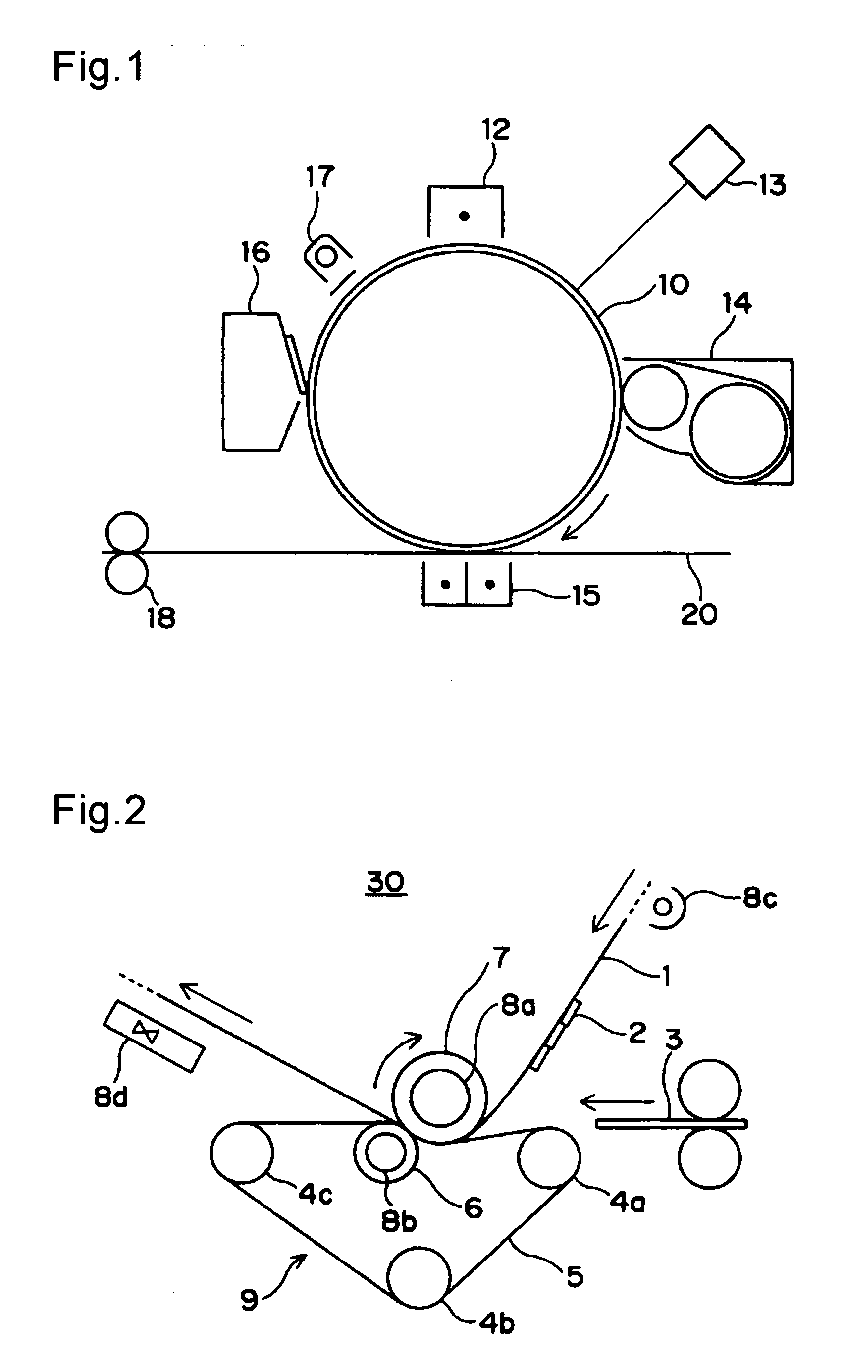
Image


Examples
example 1-1
(Formation of Core Particles)
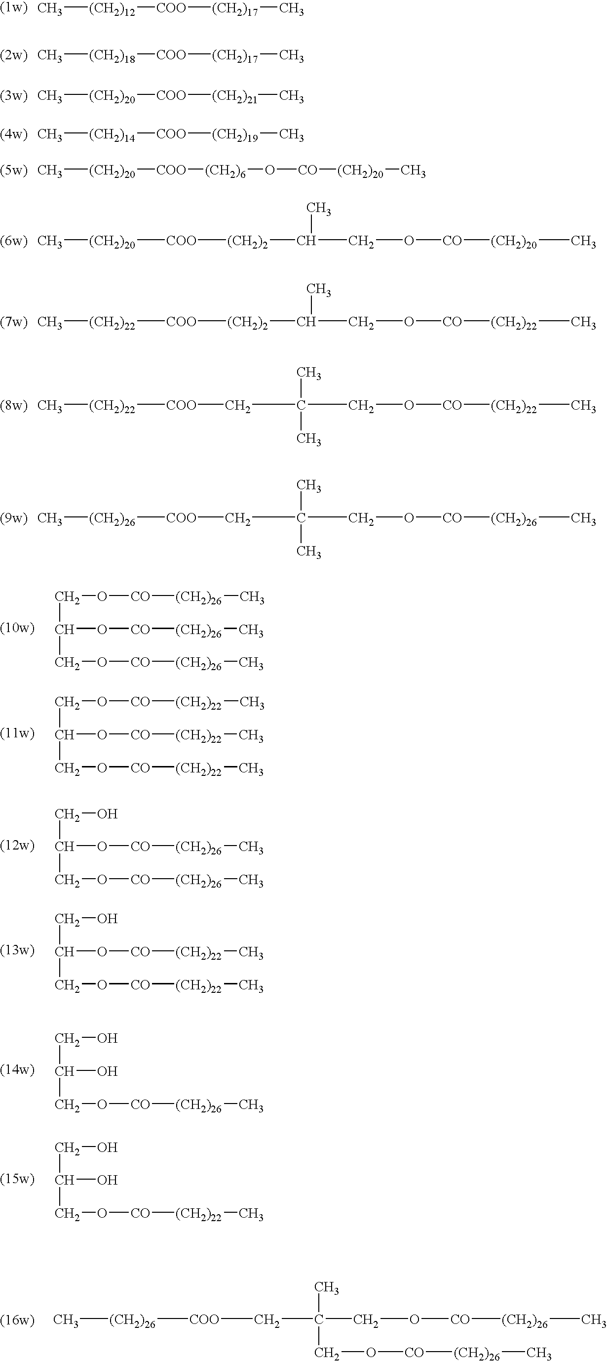
[0185]To a four-neck flask equipped with a thermometer, a cooling pipe and a stirring device were loaded 500 g of PES 2 dispersion solution and 6.4 g of anionic surfactant (Newlex R: made by NOF Corporation), and stirred at 280 rpm for 40 minutes. To this were further added 75 g of release agent dispersion solution 1 and 48 g of colorant dispersion solution C1, and the pH thereof was adjusted to 10 by using 1N NaOH aqueous solution. To this was dripped 80 g of 10 wt % magnesium chloride aqueous solution in 10 minutes, and this was then abruptly heated to 56° C. and held at this temperature for 2 hours.
(Formation of Shell Layer)
[0186]Crystalline resin 1 dispersion solution (64 g) and PES 1 dispersion solution (11 g) were preliminarily mixed, and after the resulting mixed dispersion solution had been gradually added to the system, the system was heated to 85° C. and maintained for one hour. A small amount of the resulting dispersion solution was sampled an...
example 1-2
[0187]The same processes as example 1-1 were carried out except that PES 1 dispersion solution was changed to sulfonated PES 1 dispersion solution to prepare toner particles. The toner particles had a particle size of 5.0 μm and a degree of roundness of 0.988.
example 1-3
[0188]The same processes as example 1-1 were carried out except that crystalline resin 1 dispersion solution was changed to sulfonated crystalline resin 1 dispersion solution to prepare toner particles. The toner particles had a particle size of 5.0 μm and a degree of roundness of 0.988.
PUM
 Abstract
Description
Claims
Application Information
 - R&D
- Intellectual Property
- Life Sciences
- Materials
- Tech Scout
- Unparalleled Data Quality
- Higher Quality Content
- 60% Fewer Hallucinations
Browse by: Latest US Patents, China's latest patents, Technical Efficacy Thesaurus, Application Domain, Technology Topic, Popular Technical Reports.
© 2025 PatSnap. All rights reserved.Legal|Privacy policy|Modern Slavery Act Transparency Statement|Sitemap|About US| Contact US: help@patsnap.com