
Low profile heart valve prosthesis

a heart valve and low profile technology, applied in the field of bioprosthesis, can solve the problems of reducing the hemodynamics of the valve, exposed textile coverings also tend to abrade the cusp of the valve,

Inactive Publication Date: 2007-07-24
GABBAY SHLOMO
View PDF24 Cites 244 Cited by
  • Summary
  • Abstract
  • Description
  • Claims
  • Application Information

AI Technical Summary

Benefits of technology

This design enhances hemodynamic performance, reduces the risk of structural failure, and promotes beneficial heart muscle remodeling by minimizing stent-related complications, resulting in improved blood flow and reduced tissue damage.

Problems solved by technology

While the stent provides desired rigidity and strength, which inhibits the inward deflection of the stent posts, it also decreases the hemodynamics of the valve.
The exposed textile covering also tends to abrade cusps of the valve.
In addition, stentless valves, as compared to stented valves, are more resistant to structural failure because the rigidity of a stent can cause damage to the moving cusps.

Method used


Image

  • Low profile heart valve prosthesis
  • Low profile heart valve prosthesis
  • Low profile heart valve prosthesis

Examples


Embodiment Construction

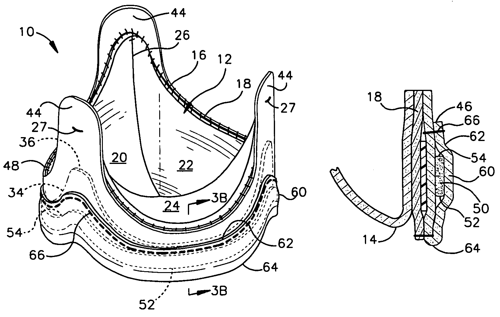
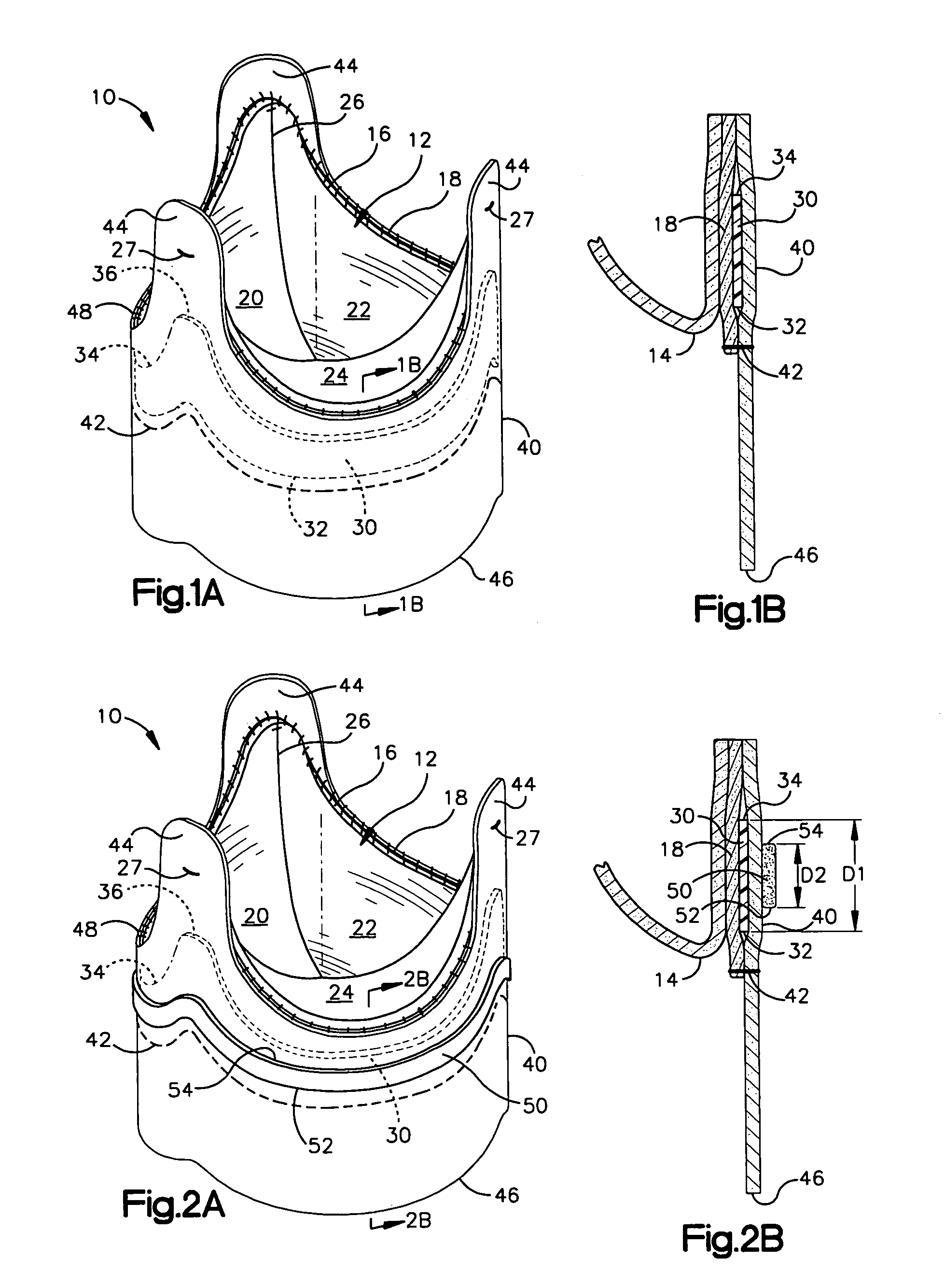
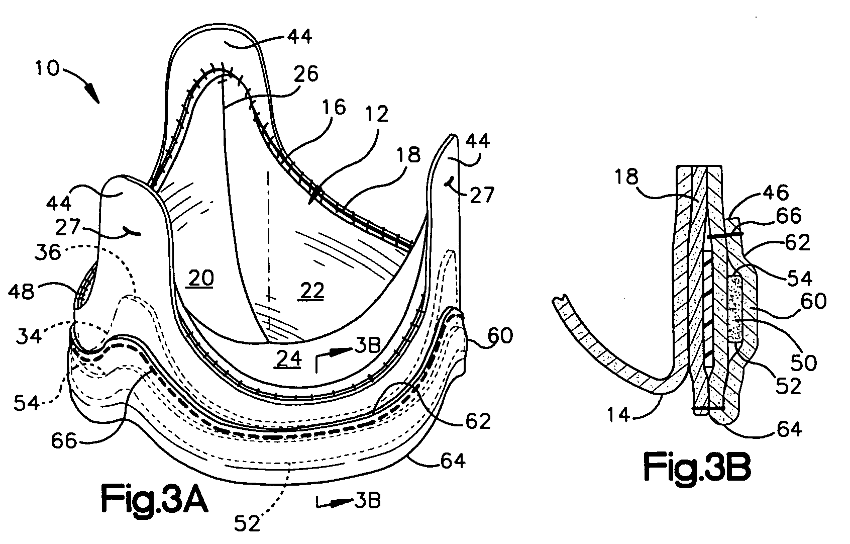
[0012]FIGS. 1A through 3B illustrate an example of one embodiment of a heart valve prosthesis 10 being fabricated in accordance with an aspect with the present invention. Each of the FIGS. 1A, 2A, and 3A correspond to different possible stages of fabrication that can be utilized to provide the prosthesis 10. The resulting prosthesis 10 is shown in FIG. 3A.

[0013]Those skilled in the art will understand and appreciate that various other approaches can be employed to produce a heart valve prosthesis according to the present invention. Additionally, it will be understood and appreciated that the relative dimensions between the various parts of the prosthesis 10 depicted in the figures are shown for purposes of simplicity of illustration and that various other dimensions and configurations can be utilized.

[0014]Throughout the various figures, the prosthesis 10 includes a valve portion 12 arranged to provide for substantially unidirectional flow of blood through the valve portion 12. The ...


PUM


Abstract

A heart valve prosthesis includes a valve member having an inflow end, an outflow end, and a generally cylindrical sidewall portion extending between the inflow end and the outflow end. The valve member includes at least one leaflet moveable relative to the sidewall portion to provide for substantially unidirectional flow of fluid through the valve member. A support of a substantially flexible material positioned is around the sidewall portion. A strip of pliant material is provided around valve member intermediate the inflow end and the outflow end of the valve member in a generally overlying relationship with the support. A covering is provided over a radially outer exposed surface of at least the strip.

Description

TECHNICAL FIELD[0001]The present invention relates to a bio-prosthesis, and more particularly to a heart valve prosthesis having a low profile.BACKGROUND OF THE INVENTION[0002]Numerous types of heart valve prostheses have been developed for replacing defective heart valves in human patients. One common type of heart valve prosthesis includes a natural tissue heart valve mounted within a stent. The stent generally provides strength and rigidity to the heart valve. Typically, the stent is covered with a textile material, such as Dacron™, which provides a substrate to which the heart valve may be secured. While the stent provides desired rigidity and strength, which inhibits the inward deflection of the stent posts, it also decreases the hemodynamics of the valve. This is because the stent substantially increases the sidewall thickness of the prosthesis, which reduces the size of the flow orifice for a prosthesis having a given outer diameter. The exposed textile covering also tends to...

Claims


Application Information

Patent Timeline
Patent Type & Authority Patents(United States)
IPC IPC(8): A61F2/24
CPCA61F2/2412
Inventor GABBAY, SHLOMO
Owner GABBAY SHLOMO
Learn More