
Device for adjusting the centering of a ring for synchronizing the control of pivoting vanes in a turbomachine

a technology of pivoting vanes and adjusting rings, which is applied in the direction of machines/engines, reaction engines, liquid fuel engines, etc., can solve the problems of not being able to remove one or more pads, not being able to adjust the clearance between the pads and the casing, and the threads of the two-thread screw to be worn completely, etc., to achieve the effect of reducing the time of assembly and disassembly, and reducing the number of parts

Active Publication Date: 2007-07-17
SN DETUDE & DE CONSTR DE MOTEURS DAVIATION S N E C M A
View PDF5 Cites 20 Cited by
  • Summary
  • Abstract
  • Description
  • Claims
  • Application Information

AI Technical Summary

Benefits of technology

[0008]A main object of the present invention is thus to mitigate such drawbacks by proposing a device for adapting the centering of the ring that is simple, reliable, and that enables time to be saved during assembly and disassembly.
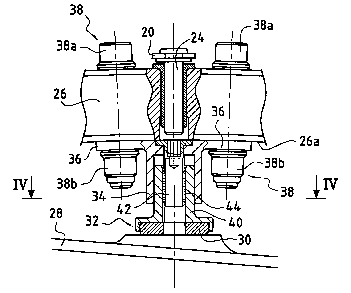
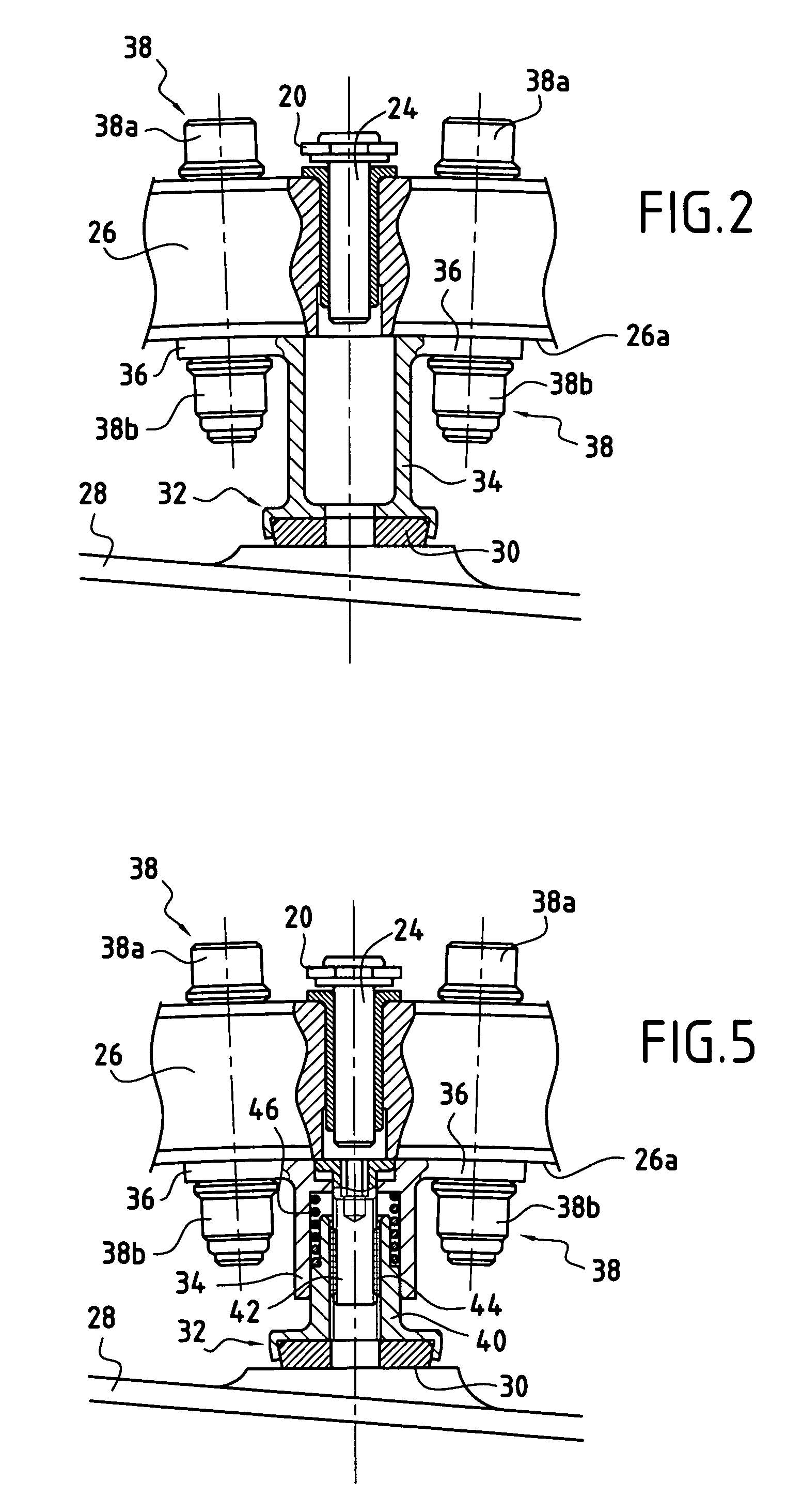
[0011]The fastening of each pad carrier under the ring by using attachment systems assembled from over the ring enables the attachment systems to be removed from the outside of the ring. When it is desired to act on a pad, there is therefore no need to remove the control ring, together with all of the parts of the variable-pitch system. As a result it is much easier to mount and dismount the pads.
[0016]Preferably, a spring is interposed between the tubular portion of the pad carrier and the tubular portion of the pad so as to provide damping for the pad on the circular surface.

Problems solved by technology

With that type of device, it has been found that during the various operating stages of the turbomachine, some of the pads are no longer in contact with the casing, thus leading to vibration, causing the threads of the two-thread screw to be worn away completely.
As a result it is no longer possible to adjust the clearance between the pads and the casing.
In addition, with that device, it is not possible to remove one or more pads without it being necessary to disassemble all of the parts of the variable-pitch vane stage, and in particular the control ring.
Thus, because of the presence of the casing, it is not possible to remove the pad from beneath the ring.

Method used


Image

  • Device for adjusting the centering of a ring for synchronizing the control of pivoting vanes in a turbomachine
  • Device for adjusting the centering of a ring for synchronizing the control of pivoting vanes in a turbomachine
  • Device for adjusting the centering of a ring for synchronizing the control of pivoting vanes in a turbomachine

Examples


Embodiment Construction

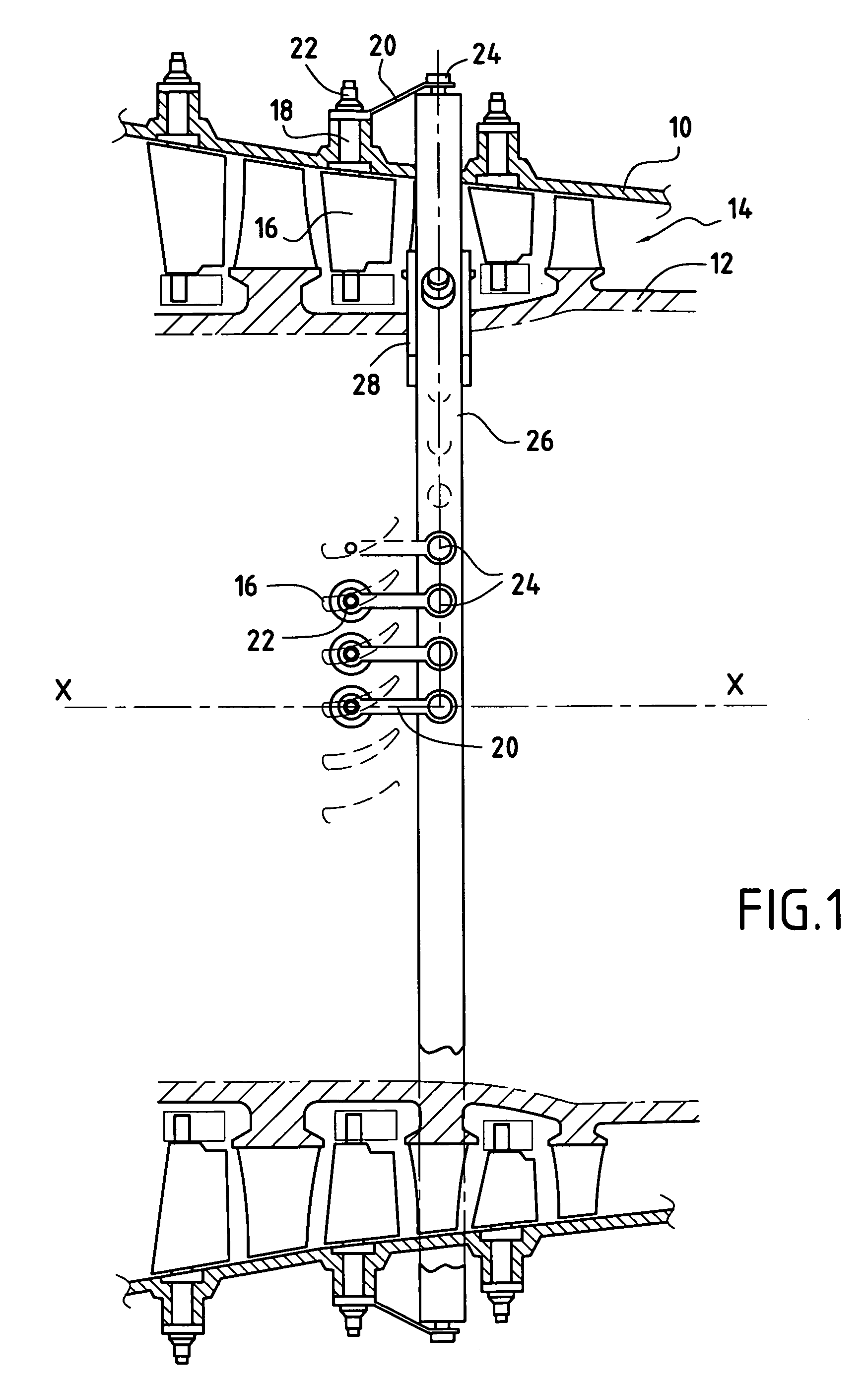
[0026]FIG. 1 shows a portion of a compressor of a turbomachine of axis X-X. The compressor comprises an annular stator casing 10 centered on the axis X-X of the turbomachine, and surrounding an annular rotor 12 in such a manner as to define an annular gas-flow section 14.

[0027]The compressor further comprises a plurality of vanes forming a plurality of stages in the flow section 14, some of which are constituted using variable-pitch vanes 16. These variable-pitch vanes 16 are mounted to pivot about respective axes 18 passing through the stator casing 10.

[0028]Each axis (or pivot) 18 of a variable-pitch vane 16 is connected at one end to a control lever or crank 20 via an endpiece 22. The other ends of the levers 20 are hinged about cranks pins 24 disposed radially on a control ring 26 that surrounds a circular surface 28 centered on the axis X-X of the turbomachine and with which it must be coaxial.

[0029]The invention relates to a device enabling the centering of the control ring 26...


PUM


Abstract

The invention provides a device for adjusting the centering of a control ring for pivoting vanes of a turbomachine, the device comprising a plurality of pads for coming into contact with a circular surface that is coaxial with the ring, each pivoting vane being connected to the control ring via a lever having a first end secured to the control ring via a crank pin disposed radially on said ring, and a second end mounted on a pivot of the vane, each of said pads being secured to a pad carrier. Each pad carrier is secured under the control ring by means of attachment systems that are designed to be assembled from over the ring.

Description

BACKGROUND OF THE INVENTION[0001]The present invention relates to the general field of devices for adjusting a ring for synchronizing the control of pivoting vanes of a turbomachine, so that the ring is properly centered on the axis of the machine.[0002]In a turbomachine, it is known to use one or more stages of stator vanes to adjust the flow and direction of the gas passing through the compression section as a function of the operating speed of the turbomachine. These stator vane stages comprise a plurality of vanes (referred to as “variable-pitch” vanes) capable of pivoting about their axes that connect them to the stator, in such a manner that their pitch angle can be modified as a function of the operating speed of the turbomachine.[0003]Known devices for controlling variable-pitch vanes conventionally comprise a control member in the form of a ring surrounding the turbomachine casing and a plurality of levers or cranks, each lever having a first end connected to the control ri...

Claims


Application Information

Patent Timeline
Patent Type & Authority Patents(United States)
IPC IPC(8): F01D17/16
CPCF01D17/162F04D29/563F05D2230/644
Inventor BROMANN, ALAIN MARC LUCIEN
Owner SN DETUDE & DE CONSTR DE MOTEURS DAVIATION S N E C M A
Learn More