Product state display system, and program and recording medium for the same

a product state display and program recording technology, applied in static indicating devices, audible signalling systems, instruments, etc., can solve the problems of reducing the endurance period (life) of the vehicle, difficult for drivers, and incorrectly understanding

Inactive Publication Date: 2007-07-10
YAMAHA MOTOR CO LTD
View PDF13 Cites 7 Cited by
  • Summary
  • Abstract
  • Description
  • Claims
  • Application Information

AI Technical Summary

Benefits of technology

[0033]Here, a “recording medium” should be used for reading a program for realizing each process in a product state display system (computer), but does not depend on a physical recording method, such as how information is recorded by utilizing physical characteristics of the medium. For example, FDs, CD-ROMs (R and RW), DVD-ROMs (RAM, R, and RW), semiconductor memories, MOs, MDs, magnetic tapes, and the like apply.

Problems solved by technology

However, when understanding the structure and the like of a product is required as in the case of the state of an engine, there arises the following problem: factors that reduce the endurance period (life) of the vehicle and that cause many failures are produced.
That is, since not every driver can understand the structure of the engine and the meaning of a particular measured value, it is difficult for the drivers and the like to correctly understand whether the state of the vehicle is normal or abnormal, what kind of condition is or could become a problem, or the like, even if information which should be displayed by use of a scale or the like, is simply replaced with the facial expression of the pseudo living matter and the state of the vehicle can be thereby recognized with an image that is familiar.
Accordingly, even when the conventional display method is used, the following problem cannot be solved: a driver unconsciously reduces the endurance period of the vehicle, or a factor that results in a failure is produced.
Moreover, although the conventional display method is suitable for the case where a condition that is temporary and can be restored by replenishment is represented, as in the case of fuel, the conventional display method is not suitable for representing a thing or condition which has an endurance period (life) and which is gradually deteriorated with time without the ability to be restored, once the thing has been deteriorated, as in the case of an engine, a lamp, or the like.
However, when a plurality of pseudo living matters are simultaneously displayed, a person who looks at them cannot understand, at first glance, what states of a product are being represented.
In particular, it is difficult for a driver of a vehicle to carefully look at a plurality of pseudo living matters while driving.

Method used


Image

  • Product state display system, and program and recording medium for the same
  • Product state display system, and program and recording medium for the same
  • Product state display system, and program and recording medium for the same

Examples


Embodiment Construction

[0044]Hereinafter, preferred embodiments of the present invention will be described using the drawings.

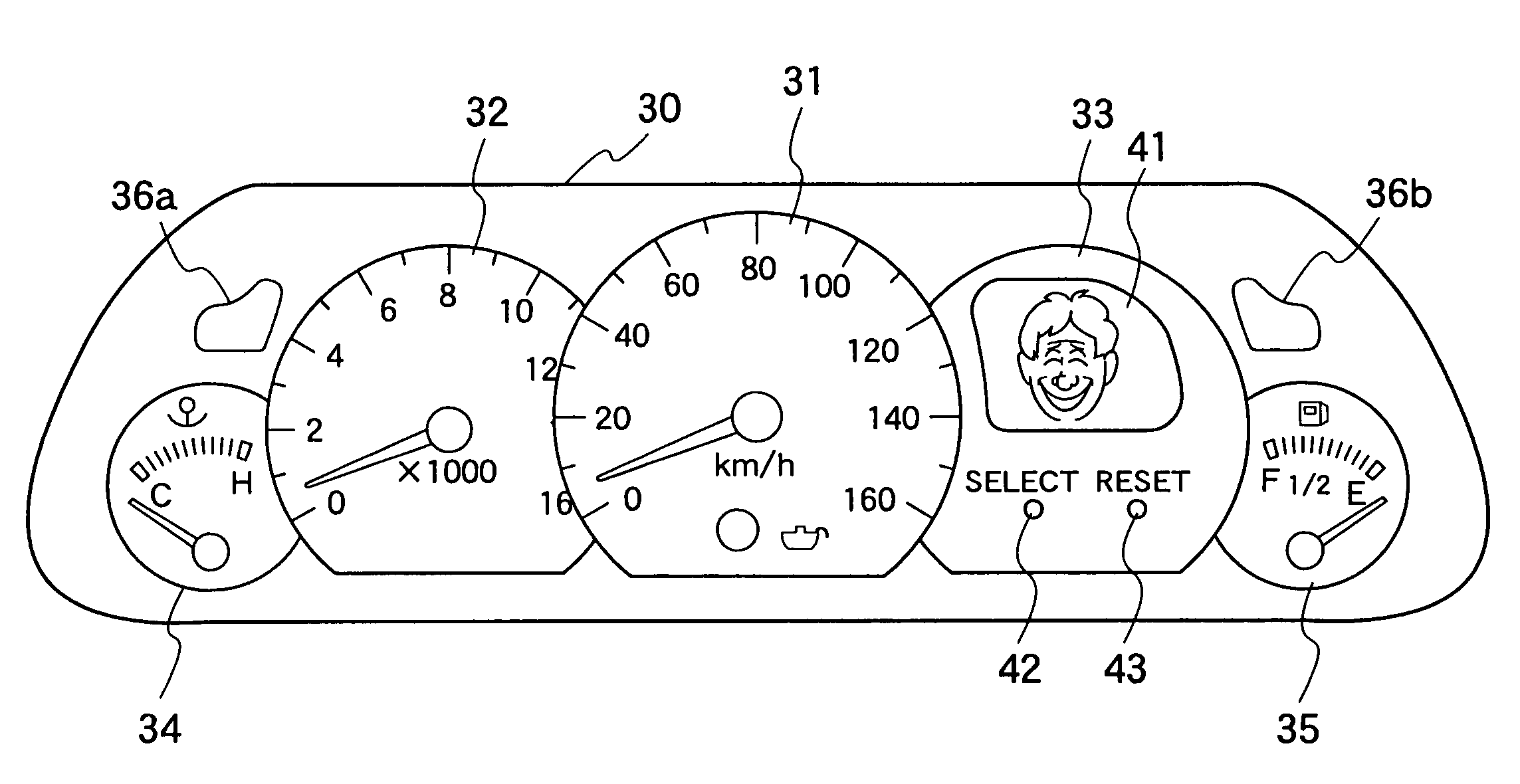
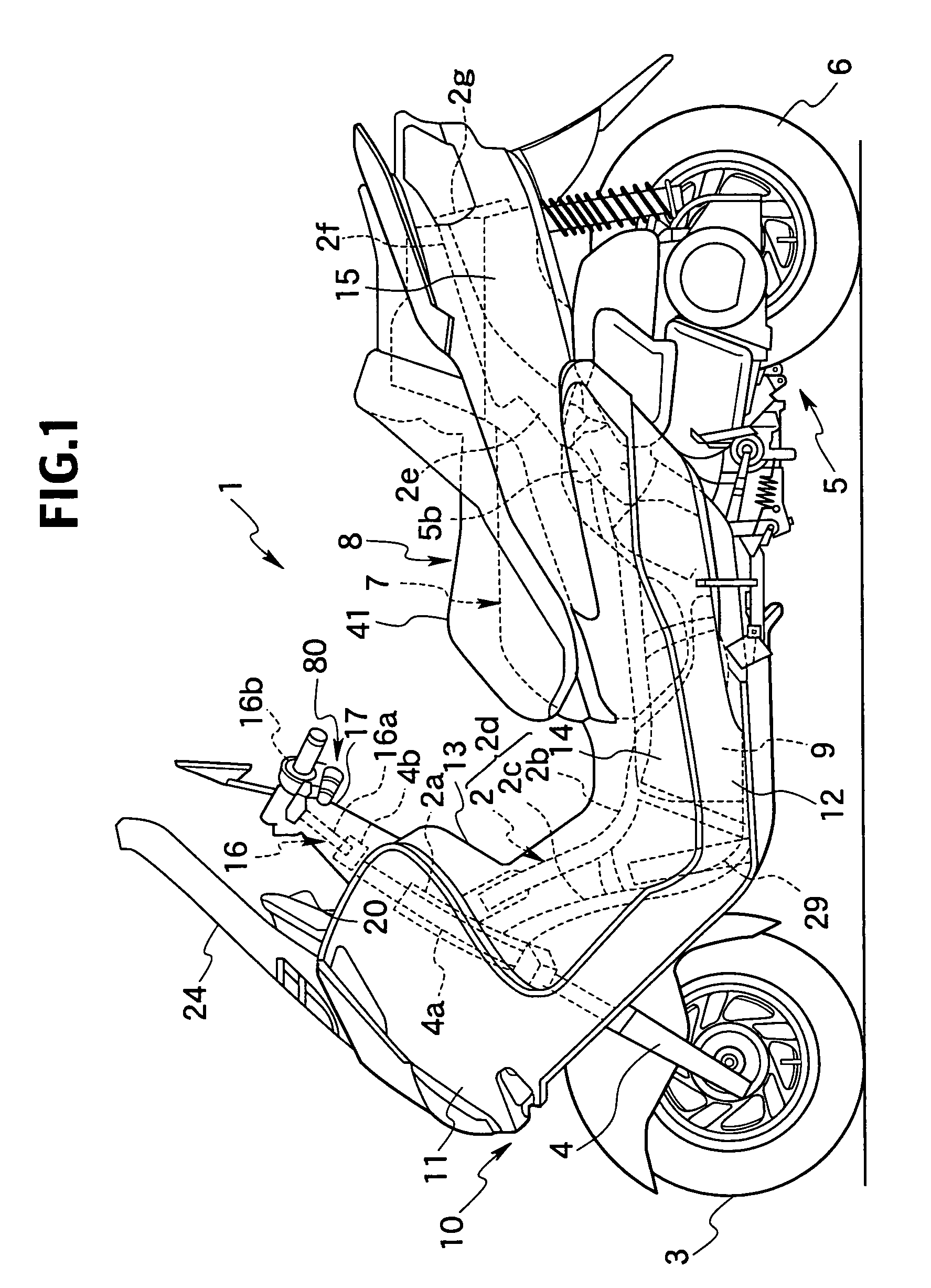
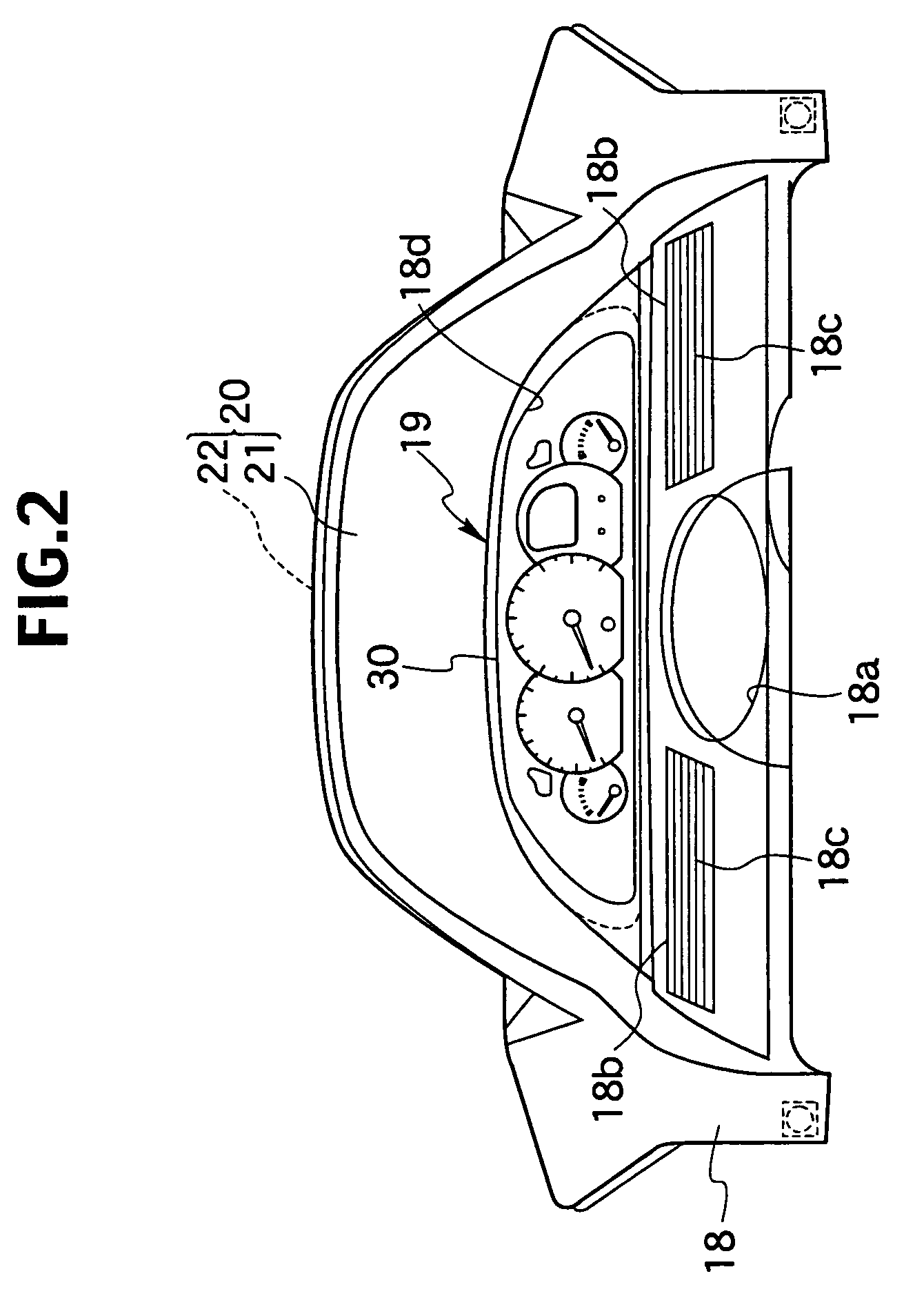
[0045]FIG. 1 is a left side view of a two-wheeled motor vehicle according to a preferred embodiment of the present invention. FIG. 2 is a rear view showing a meter panel and the surroundings thereof of a vehicle body cover. FIG. 3 is a view showing the meter panel.

[0046]In FIG. 1, reference numeral 1 denotes a scooter-type two-wheeled motor vehicle, which is an example of a product according to preferred embodiments of the present invention. This two-wheeled motor vehicle 1 preferably has the following schematic structure: a front fork 4, at the lower end of which a front wheel 3 is pivotally supported by the front end of a vehicle body frame 2 so as to allow steering to the left and the right; a unit-swing engine 5 is supported by the rear of the vehicle body frame 2 so as to be able to vertically swing; a rear wheel 6, which is placed inside of the rear end of the engine 5, is pi...


PUM


Abstract

A product state display system operates so that a person who looks at a pseudo living matter can easily understand the state of an industrial product at first glance in the case where the state of the product is represented by displaying the pseudo living matter. The pseudo living matter displayed on a display device shows both the “aging state” corresponding to the “progress state of time-dependent deterioration” of the industrial product within an endurance period and the facial expression corresponding to a “temporary state” of the industrial product. Accordingly, it is possible for a person who looks at the pseudo living matter to quickly and easily understand two states (progress state and temporary state) of the industrial product with just one glance.

Description

BACKGROUND OF THE INVENTION[0001]1. Field of the Invention[0002]The present invention relates to a product state display system for displaying a state of an industrial product, which has a changeable operating state, on a display device by use of a pseudo living matter, and relates to a program and a recording medium for the same.[0003]2. Description of the Related Art[0004]Previously, a device has been proposed in which a representation entity (hereinafter referred to as a “pseudo living matter”) designed to resemble a person, an animal, an animation character, or the like is represented as a two-dimensional or three-dimensional image in a vehicle to notify a driver of information about the state and the like of the vehicle through the pseudo living matter (Japanese Unexamined Patent Publication No. 2001-219796).[0005]The above-described state of the vehicle is a temporary state of the vehicle which has been detected by a fuel level sensor or the like, and is represented by using a...

Claims


Application Information

Patent Timeline
Patent Type & Authority Patents(United States)
IPC IPC(8): G08B3/00G08B5/00G08B7/00B60R16/02B60R16/023G09G5/00
CPCB60R16/0231G09G2340/14G09G5/00
Inventor KAMIYA, TSUYOSHI
Owner YAMAHA MOTOR CO LTD
Why Eureka
Try Eureka