Floating strainer

a strainer and hose technology, applied in water cleaning, separation processes, filtration separation, etc., can solve the problems of affecting the filtration system, so as to prevent entry.

Inactive Publication Date: 2007-07-10
TORRES COLLAZO ANGEL
View PDF23 Cites 8 Cited by
  • Summary
  • Abstract
  • Description
  • Claims
  • Application Information

AI Technical Summary

Benefits of technology

[0009]According to another aspect of the invention, a floating strainer is provided for supporting at least one intake hose of a water pumping system for withdrawing water from a lake. The floating strainer includes a rigid frame, at least one floating means, at least one anchoring means, and a strainer box. The floating means is engaged to the rigid support frame to provide buoyancy to the floating strainer assembly. The anchoring means is engaged to the rigid support frame to prevent displacement of the floating strainer assembly due to water currents. The strainer box engaged to the bottom of the rigid support frame. The strainer box has at least one aperture for installing an inlet end of the intake hose thereby preventing entry of debris and fish into the water pumping system. The strainer box, in combination with the floating means and the anchoring means, serves to support said intake hose at a predetermined depth below the surface of the lake.

Problems solved by technology

A particularly vulnerable portion of this design is found at the connection between the hose and the intake.
Because the intake rises and falls along with the float, it tends to stress and strain the joint between the intake and the hose.
Over time the joint will suffer wear and eventually may crack or separate.
A broken hose can cause serious damage to a water filtration system.
For one example, if the hose breaks away and falls to the bottom of a lake, it may draw in sand and rocks.
These can clog in-line filters and if they flow to an intake pump can cause serious damage.

Method used


Image

  • Floating strainer
  • Floating strainer
  • Floating strainer

Examples


Embodiment Construction

[0022]In the following detailed description, reference is made to the accompanying drawings which form a part hereof, and in which is shown by way of illustration, specific embodiments in which the invention may be practiced. These embodiments are described in sufficient detail to enable those skilled in the art to practice the invention, and it is to be understood that other embodiments may be utilized and that structural, procedural and system changes may be made without departing from the spirit and scope of the invention. The following detailed description is, therefore, not to be taken in a limiting sense, and the scope of the present invention is described by the appended claims.

[0023]Numbering of the figures is usually done with the hundreds and thousands digits corresponding to the figure number, with the exception that the same components may appear in multiple figures.

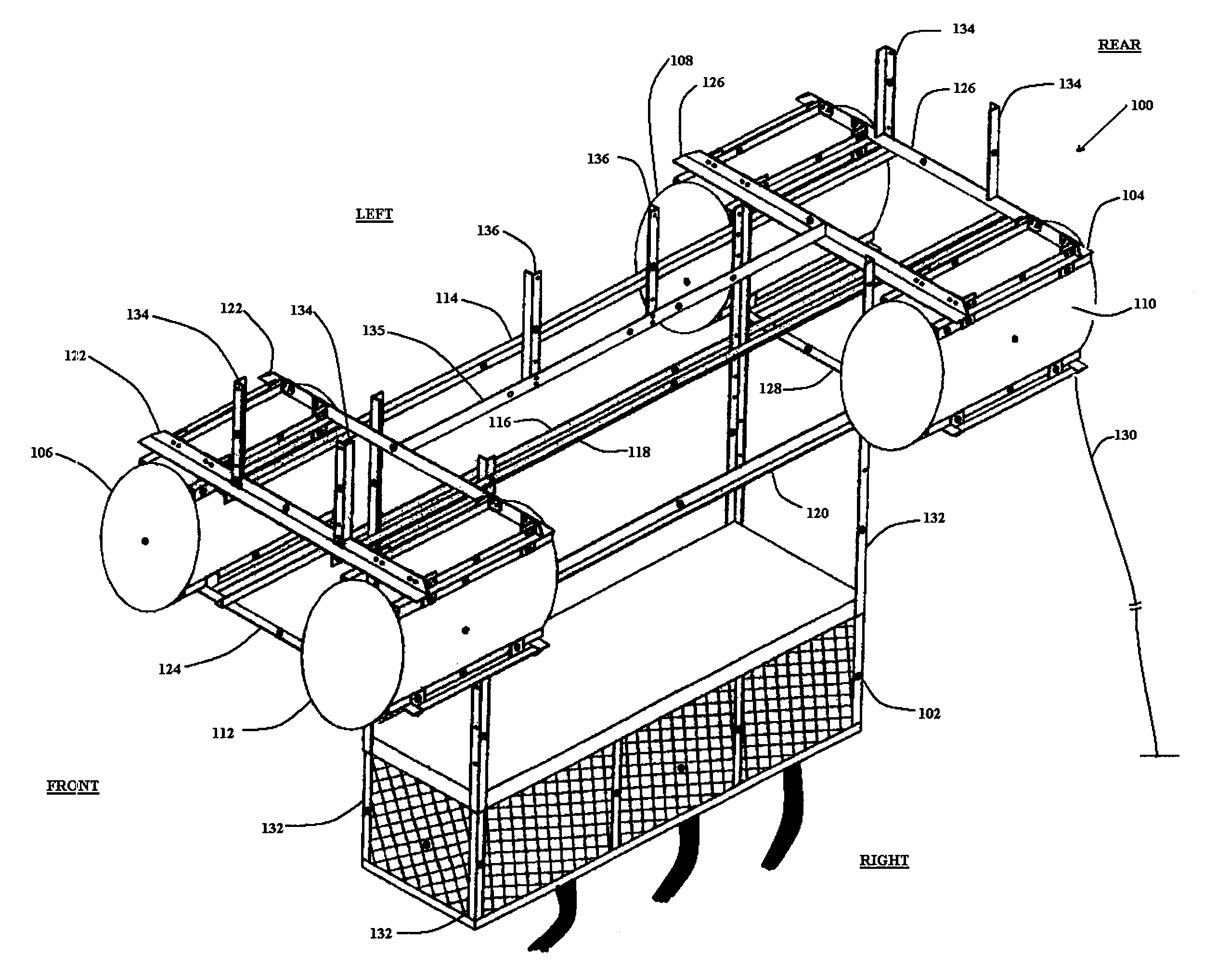
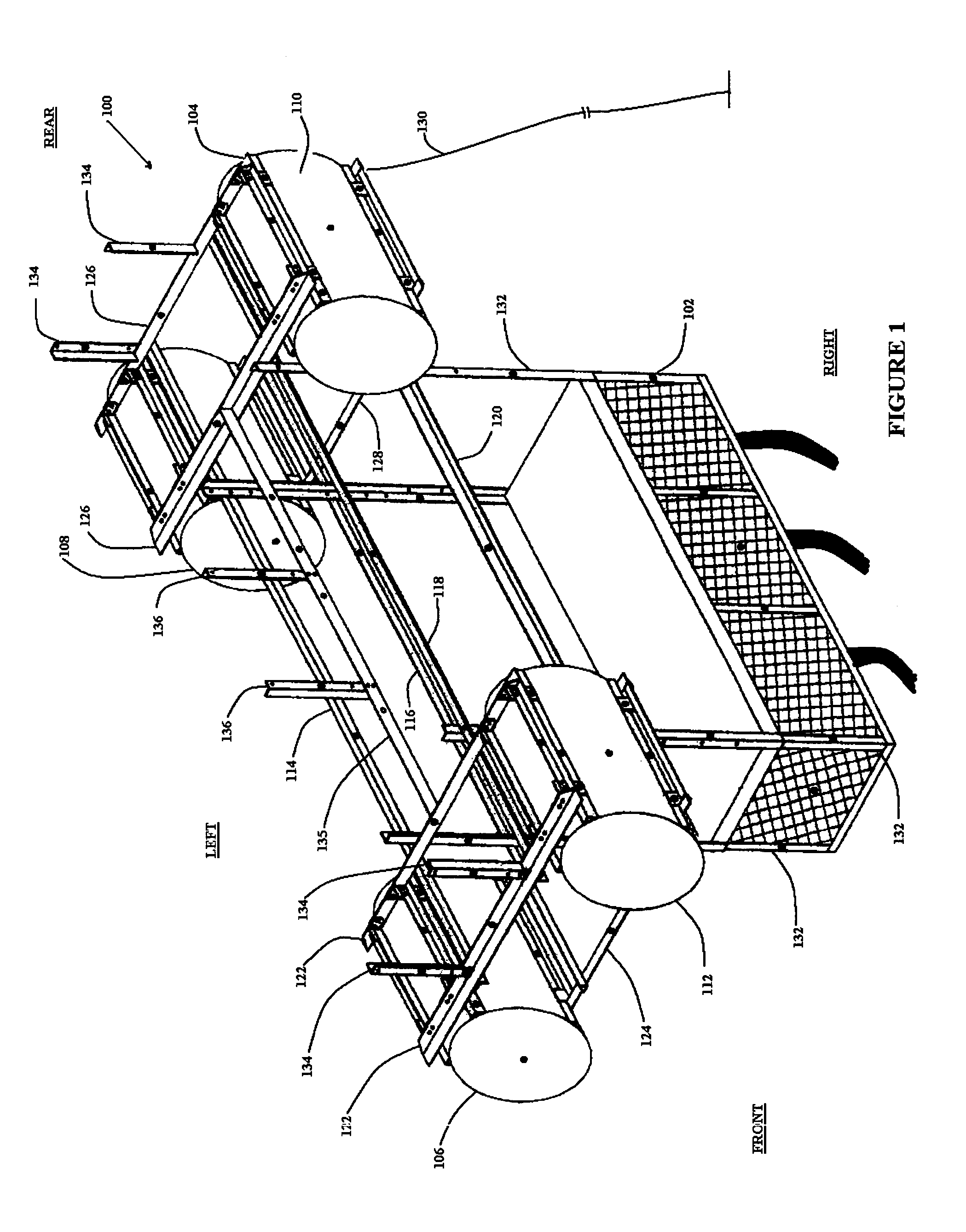
[0024]Turning to FIG. 1, one preferred embodiment of a floating strainer 100 is described. For purposes of...


PUM

PropertyMeasurementUnit
lengthaaaaaaaaaa
outer dimensionsaaaaaaaaaa
buoyancyaaaaaaaaaa

Abstract

A floating strainer is constructed having a rectangular frame. A cylindrical drum is attached to each corner of the rectangular frame. Below the rectangular frame, a box-strainer is fixed. The distance between the box-strainer and the rectangular frame is adjustable so that the level at which water is drawn can be raised or lowered. The bottom of the box-strainer includes hose connections. These are positioned so that the hoses connect at the bottom of the floating strainer and extend vertically down from the bottom. This configuration operates to distribute the weight of the hose and reduce stress and strain on the hose.

Description

PRIORITY[0001]Applicant claims the benefit of priority to U.S. Provisional Patent Application No. 60 / 615,560, which was filed on Oct. 1, 2004.FIELD OF THE INVENTION[0002]The invention relates generally to a floating strainer used to draw water from a lake or reservoir and more specifically to an improved configuration for a floating strainer that reduces wear on hoses connecting the floating strainer to a pump station.BACKGROUND OF THE INVENTION[0003]A safe supply of drinking water is a fundamental need worldwide. With growing populations, additional sources of drinking water are in ever increasing demand. Lakes and other fresh-water reservoirs provide one source from which drinking water can be drawn. An example of a system used to draw and purify water from such a source is shown in U.S. Pat. No. 5,997,750, titled “Community Drinking Water Purification System,” which issued on Dec. 7, 1999, and which is incorporated by reference in its entirety.[0004]Basically, this type of system...

Claims


Application Information

Patent Timeline
Patent Type & Authority Patents(United States)
IPC IPC(8): B01D35/05
CPCB01D35/05
Inventor TORRES-COLLAZO, ANGEL
Owner TORRES COLLAZO ANGEL
Why Eureka
Try Eureka