Tail light structure

a technology of tail light and structure, which is applied in the direction of cycle equipment, lighting and heating apparatus, light support devices, etc., can solve the problems of reducing design freedom, and achieve the effects of reducing cost, increasing design freedom, and increasing the visibleness of the light-emitting body

Active Publication Date: 2007-07-10
HONDA MOTOR CO LTD
View PDF18 Cites 5 Cited by
  • Summary
  • Abstract
  • Description
  • Claims
  • Application Information

AI Technical Summary

Benefits of technology

[0006]With the above arrangement, the reflection of external light at the first reflecting portion which receives maximum external light is suppressed, so that light from the light-emitting body is sufficiently reflected by the second reflecting portion, thus eliminating the effect of external light on the reflected light from the light-emitting body. Visibility of the light-emitting body can be increased. Since the reflecting portion needs to be improved only, limitations on the shaping of the vehicle body are not posed, the appearance of the vehicle body is not adversely affected, and the freedom of design is increased.
[0007]The tail light structure may further be characterized in that the first reflecting portion has a coating for preventing external incident light from being reflected. With this arrangement, since only the portion which receives much external light may have a coating applied, the tail light structure can be manufactured simply by coating certain regions of general-purpose products, resulting in a reduction in the cost.
[0008]The tail light structure may also be characterized in that the first reflecting portion has a structure for reducing external incident light from being reflected. Rather, the reflecting surface is only required to be formed without the need for any special subsequent processing, so that the tail light structure can be manufactured at a reduced cost. External incident light may be scattered by the first reflecting portion having a convex or prism cut reflecting surface. With this arrangement, it is not necessary to use any special members for preventing external incident light from being reflected.
[0009]The light emitting body of the tail light structure may comprise a light-emitting diode. With this arrangement, the tail light structure can suppress heating and can be of a low profile. Therefore, the tail light structure can be designed with increased freedom, e.g., can be shaped and placed with increased freedom, for improved appearance.

Problems solved by technology

However, such a solution poses the problem of reduced design freedom.

Method used


Image

  • Tail light structure
  • Tail light structure
  • Tail light structure

Examples


Embodiment Construction

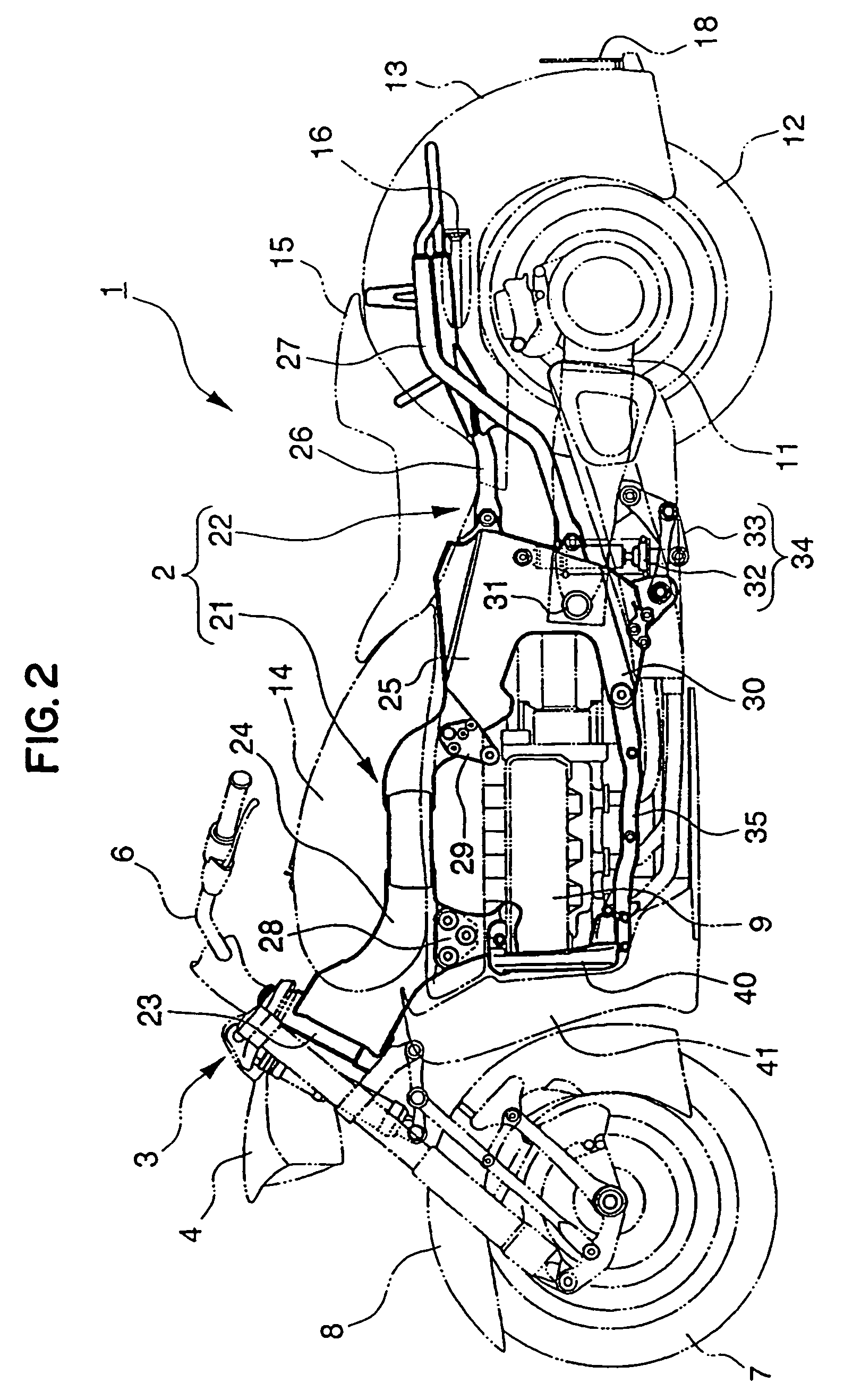
[0027]Embodiments of the present invention will be described below with reference to the drawings. FIGS. 1 through 15 show a first embodiment of the present invention.

[0028]As shown in FIGS. 1 and 2, a motorcycle 1 is of the so-called American type, and has a vehicle frame 2, a linkage front suspension 3 angularly movably supported on a front end of the vehicle frame 2, a head light 4 mounted on an upper portion of the front suspension 3, a pair of left and right front blinkers 5 disposed below the head light 4, and a steering handle 6 mounted on an upper end of the front suspension 3 and disposed on an upper front portion of the vehicle body.

[0029]The motorcycle 1 also has a front wheel 7 rotatably supported on the front suspension 3, a front fender 8 supported on the front suspension 3 in covering relation to an upper side of the front wheel 7, an engine 9 supported on the vehicle frame 2, a radiator 10 disposed forwardly of the engine 9, a rear swing arm 11 mounted on a rear port...


PUM

PropertyMeasurementUnit
reflectanceaaaaaaaaaa
light structureaaaaaaaaaa
poweraaaaaaaaaa

Abstract

A tail light structure having a light-emitting body and a reflector member for reflecting light from the light-emitting body for external illumination. The reflector member has a lower reflecting surface for receiving maximum external light and an upper reflecting surface and left and right reflecting surfaces, and the lower reflecting surface having a lower reflectance than the upper reflecting surface and the left and right reflecting surfaces.

Description

FIELD OF THE INVENTION[0001]The present invention relates to a tail light structure for motorcycles or the like.BACKGROUND OF THE INVENTION[0002]Some motorcycles or the like, for example, employ light-emitting diodes as tail lights. Such a tail light has a reflecting plate disposed around the light-emitting diode for reflecting light from the light-emitting diode for keeping visibility. For example, the tail light structure disclosed in Japanese patent laid-open No. Hei 6-24371.[0003]The conventional tail light structure described above is advantageous in that its power consumption is small because it employs the light-emitting diode. However, if sunlight is applied to the tail light structure and is reflected by the reflecting plate in daytime, then the reflected sunlight is possibly mixed with the reflected light of the light-emitting diode. In view of this drawback, the tail light structure may be so shaped that it is disposed in a location where sunlight is less likely to be app...

Claims


Application Information

Patent Timeline
Patent Type & Authority Patents(United States)
IPC IPC(8): B62J6/00F21S8/10F21V21/00F21V33/00F21V7/00B60Q1/26B60Q1/30B62J6/04F21W101/14F21W107/17F21Y101/02
CPCB60Q1/2696B60Q1/30B62J6/04B62J6/20
Inventor MIYAGAWA, TORUHIKICHI, KOICHISHIMAMURA, KOICHI
Owner HONDA MOTOR CO LTD
Why Eureka
Try Eureka