
Conveyance method and apparatus for processing step

a technology of conveying apparatus and processing step, which is applied in the direction of charging, ways, furniture, etc., can solve the problems of angular position control of the vehicle body with respect to its angular position, and the inability to control the position of the conveyed object. , to achieve the effect of reducing equipment costs and maintenance costs and easy control of the conveyed object position

Inactive Publication Date: 2007-07-03
TAIKISHA LTD +1
View PDF9 Cites 11 Cited by
  • Summary
  • Abstract
  • Description
  • Claims
  • Application Information

AI Technical Summary

Benefits of technology

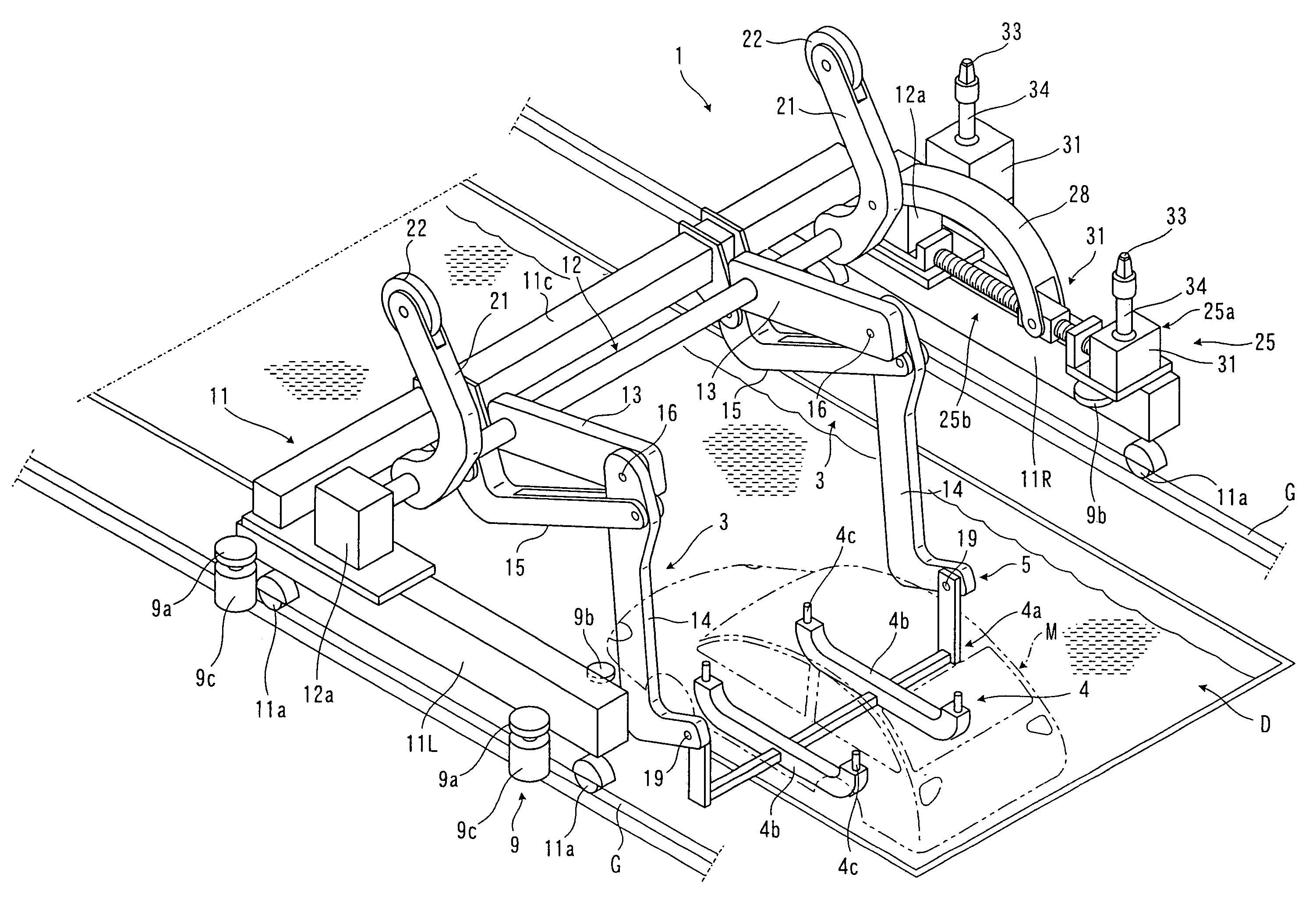
[0008]According to the invention described in a preferred embodiment, it is possible to cause the second arm, which is raised and lowered in combination with the first arm due to the swinging link mechanism, to rotate in a prescribed direction, by means of the third arm, and hence the supporting body which is supported on the free end section of the second arm is raised and lowered, thereby being introduced into the processing liquid in a processing liquid tank and being removed from same, along a movement path that follows a substantially vertical direction. Consequently, it is possible to raise or lower the supporting body in a substantially vertical direction, by means of a swinging link mechanism having a simple composition, and accordingly, equipment costs and maintenance costs can be reduced, and the position of the conveyed object can be controlled readily. Furthermore, since the conveyed object can be introduced into and removed from the processing liquid in a substantially vertical direction, then the processing liquid tank can be designed in a more compact fashion, in comparison with prior art examples in which the conveyed object is raised and lowered, and hence introduced into the processing liquid and removed from same, following an arc-shaped direction.
[0010]According to the invention described in the preceding paragraph, a supporting body supported on the free end section of a swinging link mechanism can be raised or lowered by the swinging link mechanism along a movement path following a substantially vertical direction, and hence it can be introduced into and removed from the processing liquid in the processing liquid tank, and furthermore, equipment costs and maintenance costs can be reduced by adopting a swinging link mechanism having a simple composition and the position of the conveyed object can be controlled readily.

Problems solved by technology

Furthermore, if the direction of descent and ascent is an arc-shaped direction, then a problem arises in that the positional control of the vehicle body, and the control of the angular position of the vehicle body with respect to its angular position when immersed in the treatment liquid and its angular position when removed from same, become complicated.

Method used


Image

  • Conveyance method and apparatus for processing step
  • Conveyance method and apparatus for processing step
  • Conveyance method and apparatus for processing step

Examples


second embodiment

Description of Second Embodiment of Conveyance Truck

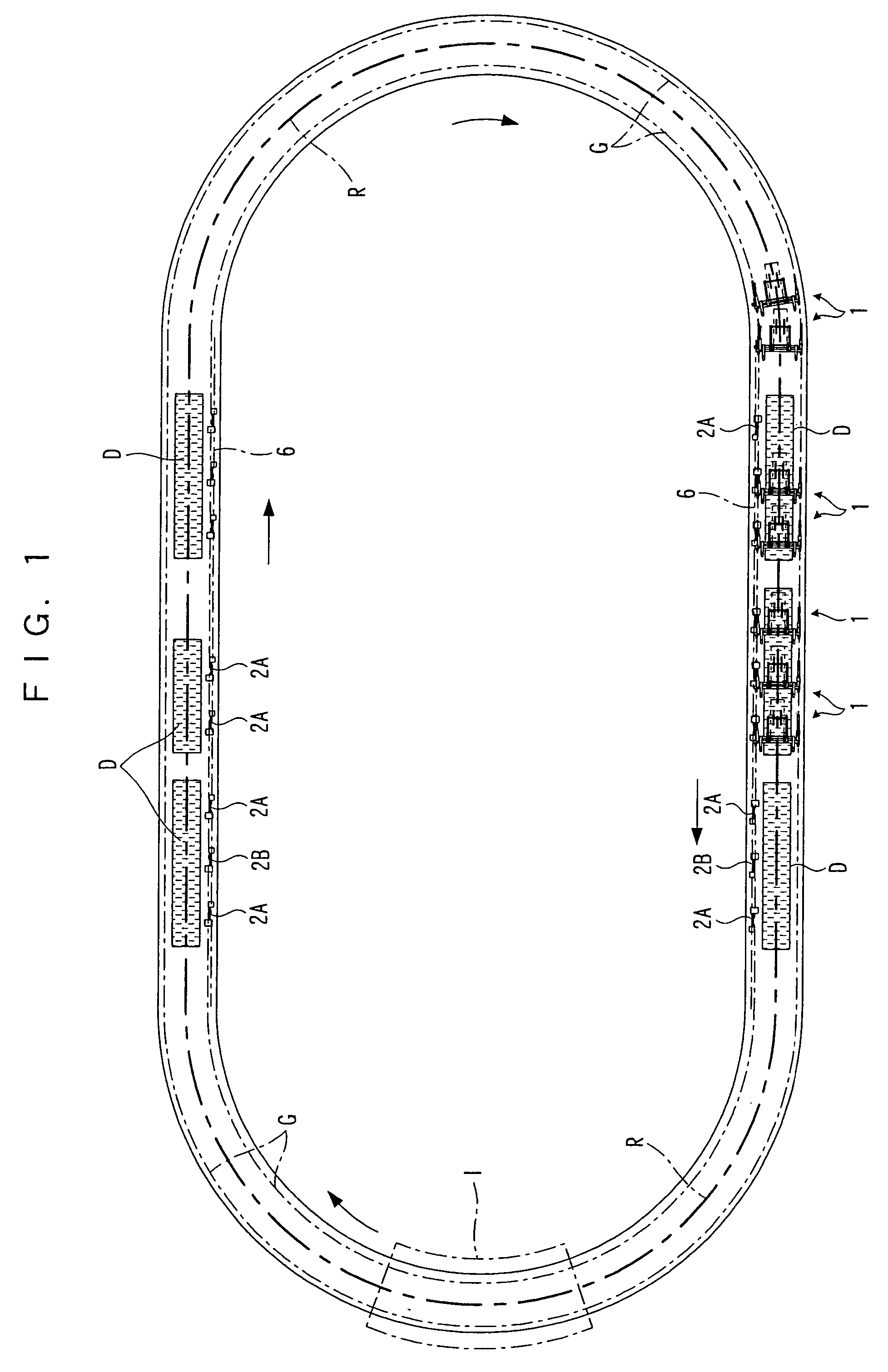
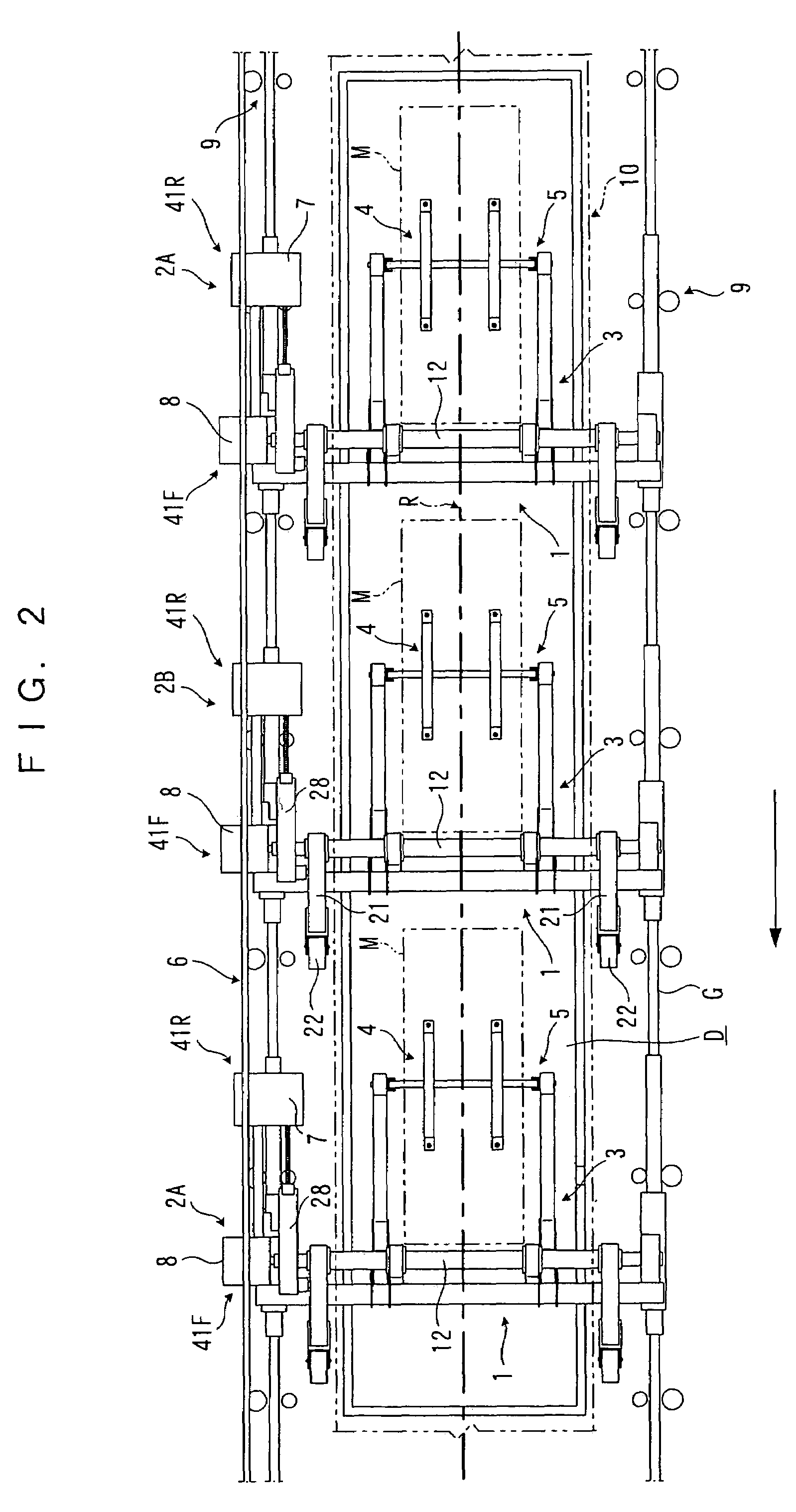
[0062]On the other hand, a right-side travel beam 11R of the conveyance truck 1 is positioned below the accompanying trucks 2A, 2B which move in synchronism with a conveyance truck 1. A first passive device 25 for receiving the drive force of the first drive device 7 and a second passive device 26 for receiving the drive force of the second drive device 8 are provided on this right-side travel beam 11R. The first passive device 25 causes the outer axle 12o of the support axle 12 to rotate, by means of a right-side passive lever 21. The second passive device 26 drives the inner axle 12i of the support axle 12 in rotation.

[0063]The first passive device 25 comprises a passive section 25a disposed in the rear portion of the right-side travel beam 11R, which is capable of coupling to and decoupling from the first drive device 7, and a lever type rotating section 25b which transmits drive force input to the passive section 25a, to the ou...


PUM


Abstract

A swinging link mechanism, provided on a conveyance truck, for raising and lowering a vehicle body held on a supporting member includes a first arm having a fixed end section which is attached to the conveyance truck in a vertically rotatable manner by means of a horizontally oriented support axle, a second arm having a fixed end section supported rotatably on the free end section of the first arm and having a supporting member provided on the free end section thereof, and a third arm coupled rotatably between the conveyance truck and a prescribed position on the second arm. Third arm is caused to rotate the second arm in the opposite direction to the first arm in response to rotation of the first arm, thereby to make the lower movement path of the supporting member to extend substantially vertically. Hence, the vehicle body can be raised or lowered in a substantially vertical movement path, and the position and attitude of the vehicle body can be controlled readily, by adopting a link mechanism of a simple configuration.

Description

BACKGROUND OF THE INVENTION[0001]1. Field of the Invention[0002]The present invention relates to a conveyance method and apparatus for a processing step, used in a conveyance line in which processing is carried out, such as a coating line or a machining line, or the like, in a manufacturing plant.[0003]2. Description of the Related Art[0004]A prior art example of a conveyance apparatus whereby a vehicle body is coated whilst being conveyed is disclosed in International Patent WO 02 / 053482. This conveyance apparatus is provided with a conveyance truck that is able to travel over immersion tanks, and pairs of swinging arms are provided on the conveyance truck, as two sets, at the front section and at the rear section in the direction of travel. Supporting bars are installed respectively between the free end sections of the pairs of swinging arms, and a vehicle body is supported on top of the front side supporting bar and the rear side supporting bar. By causing the front and rear side...

Claims


Application Information

Patent Timeline
Patent Type & Authority Patents(United States)
IPC IPC(8): B05D1/18B05C13/00B62D65/00B65G49/04
CPCB65G49/0459B65G2201/0294B62D65/028B60Y2304/05
Inventor KYOTANI, HISASHI
Owner TAIKISHA LTD
Learn More