
Slide-out mechanism for recreational vehicles

a slide-out mechanism and recreational vehicle technology, applied in the field of recreational vehicles, can solve the problems of affecting the reliability of the extendable rail during deployment and retraction, the size of the slide-out is limited, and the structure can deform or warp, so as to improve the weight distribution of the slide-out

Inactive Publication Date: 2007-07-03
ALFA LEISURE
View PDF16 Cites 4 Cited by
  • Summary
  • Abstract
  • Description
  • Claims
  • Application Information

AI Technical Summary

Benefits of technology

[0009]The aforementioned needs may be satisfied by a recreational vehicle comprising a vehicle frame having a plurality of wheels and a coach having a slide-out mounted on the vehicle frame. In one embodiment, the recreational vehicle may comprise an armature having a fixed member with a roller and a guiding channel mounted to the vehicle frame and a rail member slidably positioned within the fixed member so as to contact the roller, wherein the rail member is adapted to telescopically extend from the fixed member through the guiding channel so as to deploy and retract the slide-out. In addition, the recreational vehicle may further comprise an actuator having a first gearing mechanism displaced from the roller a first distance and housed within the guiding channel so as to contact the rail member at the first distance, wherein the first gearing mechanism can be displaced from the roller at a second distance that is greater than the first distance so as to improve the weight distribution of the slide-out. In one aspect, the actuator may comprise a second gearing mechanism mounted to the guiding channel at the first distance.
[0010]Also, the actuator may further comprise a motor functionally coupled to the second gearing mechanism so as to communicate therewith and provide a motive force thereto. The second gearing mechanism may be functionally coupled to the first gearing mechanism so as to communicate therewith and to transfer the motive force of the motor to the first gearing mechanism. The first gearing mechanism may be adapted to receive the motive force from the second gearing mechanism and operates so as to deploy and retract the rail member from the fixed member of the armature, which results in deployment and retraction of the slide-out via the first exterior sidewall of the coach. The second gearing mechanism may be mounted to the fixed member at a selectable distance from the first gearing mechanism so as to allow the motor to be displaced from the guiding channel at the selectable distance along the length of the fixed member. The first gearing mechanism may be mounted to the guiding channel at the second distance so as to improve the weight distribution of the slide-out relative to the roller during deployment and retraction of the slide-out.
[0011]Additionally, the aforementioned needs may also be satisfied by a recreational vehicle having a vehicle frame with a plurality of wheels and a coach having a slide-out mounted on the vehicle frame. In one embodiment, the recreational vehicle may comprise a fixed member having a roller mounted to the vehicle frame and a guiding channel mounted to the vehicle frame so as to be horizontally aligned with the fixed member, a rail member slidably attached to the fixed member so as to contact the roller, wherein the rail member is adapted to distally extend from the fixed member through the guiding channel so as to deploy and retract the slide-out from and into the coach. Moreover, the recreational vehicle may further comprise a first gearing mechanism displaced from the roller a first distance and mounted to the guiding channel so as to contact the rail member at the first distance and a second gearing mechanism displaced from the roller a second distance and housed within the guiding channel so as to contact the rail member during distal extension from the fixed member to thereby improve the weight distribution of the slide-out relative to the roller during deployment and retraction of the slide-out.

Problems solved by technology

Structural limitations of the vehicle frame typically restrict the position of the extendable rails such that the extendable rails have to leverage the weight of the slide-out over a short distance due to the restricted positioning of the extendable rails with respect to the vehicle frame.
Unfortunately, the support structures can deform or warp over time and through excessive use, which can adversely effect the reliability of the extendable rails during deployment and retraction.
Moreover, the size of the slide-out is limited by weight, wherein typical extendable rails could not support a large slide-out due to the lack of structural support for heavy slide-out structures.

Method used


Image

  • Slide-out mechanism for recreational vehicles
  • Slide-out mechanism for recreational vehicles
  • Slide-out mechanism for recreational vehicles

Examples


Embodiment Construction

[0020]Reference will now be made to the drawings wherein like numerals refer to like parts throughout. An improved mechanism for deploying and retracting recreational vehicle slide-outs will be described in greater detail herein below with reference to the drawings.

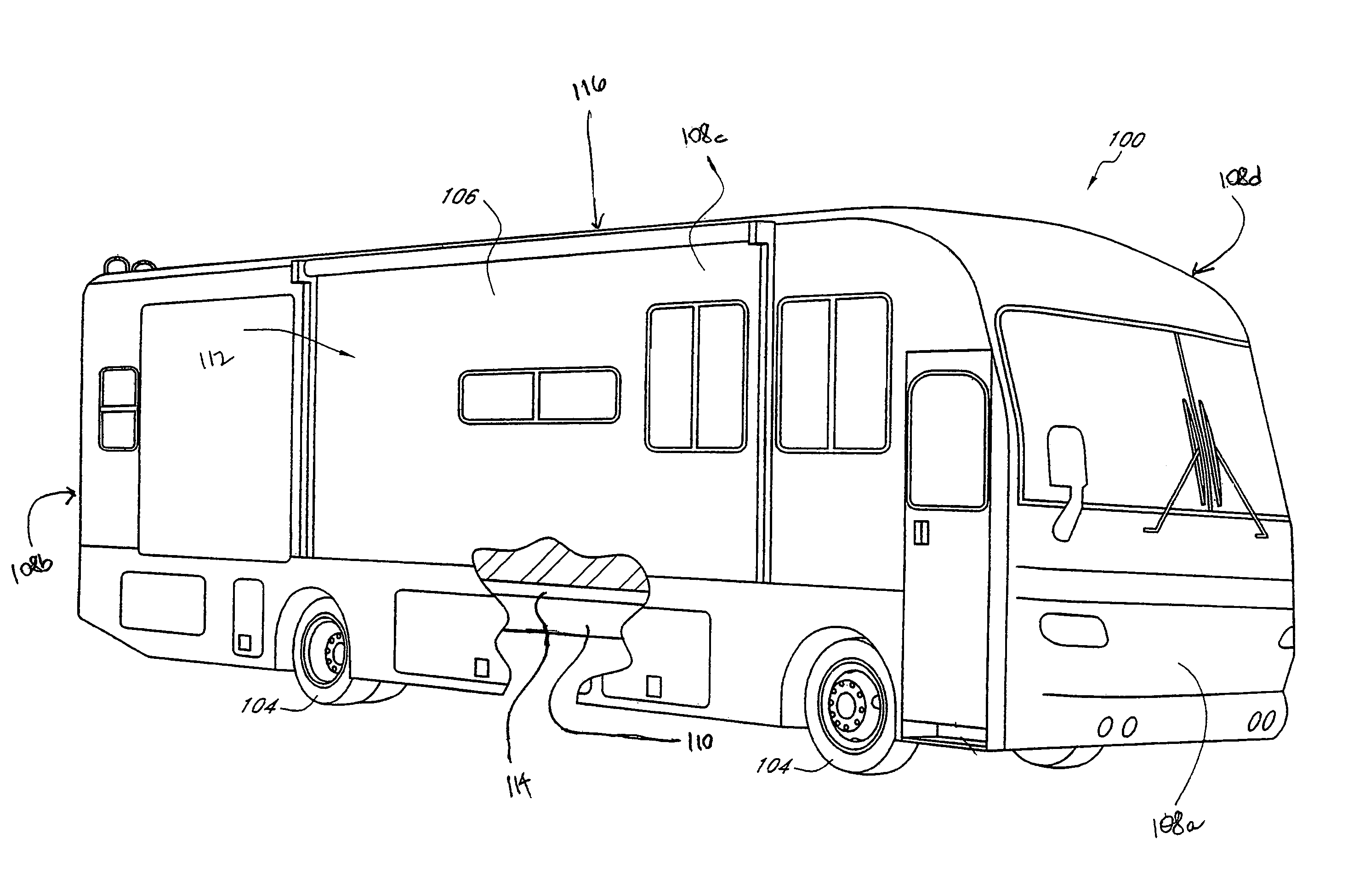
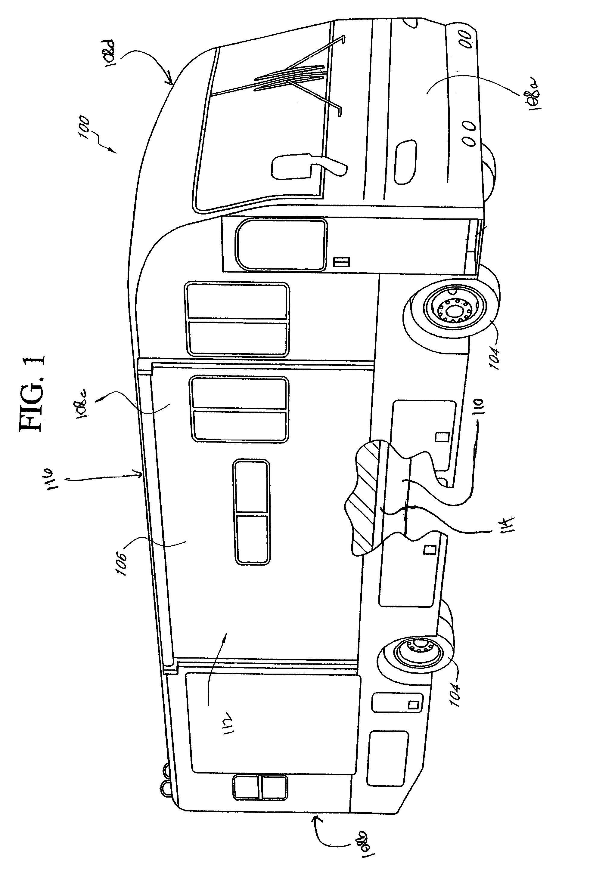
[0021]FIG. 1 illustrates one embodiment of a recreational vehicle (RV) 100 having a generally rectangular chassis 102 (shown in FIG. 2) attached to a plurality of wheels 104 so as to permit rolling movement of the RV 100 over the ground. The RV 100 further comprises a coach or coach 106 that is essentially formed of a plurality of exterior planar walls 108a, 108b, 108c, 108d that are joined together and mounted to a vehicle frame 110 in a generally known manner so as to define an interior living space 112 having a coach floor 114 and coach roof 116. A horizontal axis, which is substantially parallel to the coach floor 114, extends from a front planar wall 108a of the RV 100 to a rear planar wall 108b of the RV 100. Also, ...


PUM


Abstract

A recreational vehicle comprising a vehicle frame having a plurality of wheels and a coach having a slide-out mounted on the vehicle frame is disclosed herein. In particular, the recreational vehicle comprises an improved slide-out mechanism for deploying and retracting slide-out structures from the coach of the recreational vehicle. In one aspect, the recreational vehicle may comprise an armature having a fixed member with a roller and a guiding channel mounted to the vehicle frame and a rail member slidably positioned within the fixed member so as to contact the roller, wherein the rail member is adapted to telescopically extend from the fixed member through the guiding channel so as to deploy and retract the slide-out. Also, the recreational vehicle may further comprise an actuator assembly having a first gearing mechanism displaced from the roller a first distance and housed within the guiding channel so as to contact the rail member at the first distance, wherein the first gearing mechanism can be displaced from the roller at a second distance that is greater than the first distance so as to improve the weight distribution of the slide-out.

Description

CLAIM OF PRIORITY[0001]This application claims the benefit of U.S. Provisional Application No. 60 / 645,145, filed on Jan. 19, 2005, entitled “SLIDE-OUT MECHANISM FOR RECREATIONAL VEHICLES,” which is hereby incorporated by reference in its entirety.BACKGROUND[0002]1. Field[0003]The present teaching relates to recreational vehicles and, in particular, relates to an improved mechanism for deploying and retracting recreational vehicle slide-outs.[0004]2. Description of the Related Art[0005]Recreational vehicles are becoming increasingly popular with people who wish to retain the comforts and conveniences of home while spending extended periods of time away from home at remote locations. In more elaborate configurations, the recreational vehicle typically includes interior living areas with amenities and convenience fixtures, such as a bedroom area with a bed and wardrobe closet, a bathroom area with a sink, a flushing toilet, a shower, and a washing machine, a kitchen with a refrigerator...

Claims


Application Information

Patent Timeline
Patent Type & Authority Patents(United States)
IPC IPC(8): B60P3/34
CPCB60P3/34
Inventor CREAN, JOHNNIE R.BROWN, RON
Owner ALFA LEISURE
Learn More