
Systems and methods for diagnosing faults in computer networks

a computer network and system technology, applied in the field of systems and methods for diagnosing faults in computer networks, can solve problems such as network blasters, slow access, redundancy loss, etc., and achieve the effect of minimizing the burden on an already degraded network environmen

Inactive Publication Date: 2007-06-26
COMP ASSOC THINK INC
View PDF106 Cites 65 Cited by
  • Summary
  • Abstract
  • Description
  • Claims
  • Application Information

AI Technical Summary

Benefits of technology

[0040]According to yet another aspect, when modeling the communications network, the system generates source to destination paths by following the standards-based routing and forwarding algorithms employed by the network devices. Then, by examining the actual application dependencies and the network elements in the path, the system efficiently diagnoses various problems thereby minimizing the burden on an already degraded network environment. Additionally, the combination of application dependencies and path analysis allows the system to generate the impact of network degradation. Based on the accessibility of these applications, users can be informed about important problems. Furthermore, the network management system can intelligently adjust its monitoring of the degraded section of the network until the problem is remedied. Finally, the system can use path analysis as a tool to verify that problems have been fixed.
[0041]The present system provides a collection of autonomous or integrated network fault detectors and service disruption detectors that report symptoms of network faults. Based on the reported symptoms, a fault object factory creates fault objects in a shared fault repository. A fault diagnosis engine (which is a generic fault-processing engine) triggers fault handlers that include fault testers and fault diagnosers. The fault diagnosers are registered for notification of faults of a specific type entering a specific state. Fault diagnosers use the rich topology model of the network and services, efficient data path determination, and innovative analysis techniques to find related faults. By finding and analyzing related faults, the system ultimately finds the root cause fault. The fault diagnosers may also detect new related or unrelated faults and the fault object factory then creates new fault objects for the fault repository. Using the fault objects the system constructs a fault causality tree. As a result, the root cause fault is diagnosed and the impact of the fault is determined.

Problems solved by technology

For example, network fault conditions includes no-access faults, slow access (bottlenecks), redundancy loss, network blasters (i.e., entities emitting excessive amounts of traffic), obstacles (e.g., when one entity prevents another entity from achieving maximum throughput), stale or misplaced static routing information, incorrect network policies, packet filtering or ACL misplacement, or denial of service attacks.

Method used


Image

  • Systems and methods for diagnosing faults in computer networks
  • Systems and methods for diagnosing faults in computer networks
  • Systems and methods for diagnosing faults in computer networks

Examples


Embodiment Construction

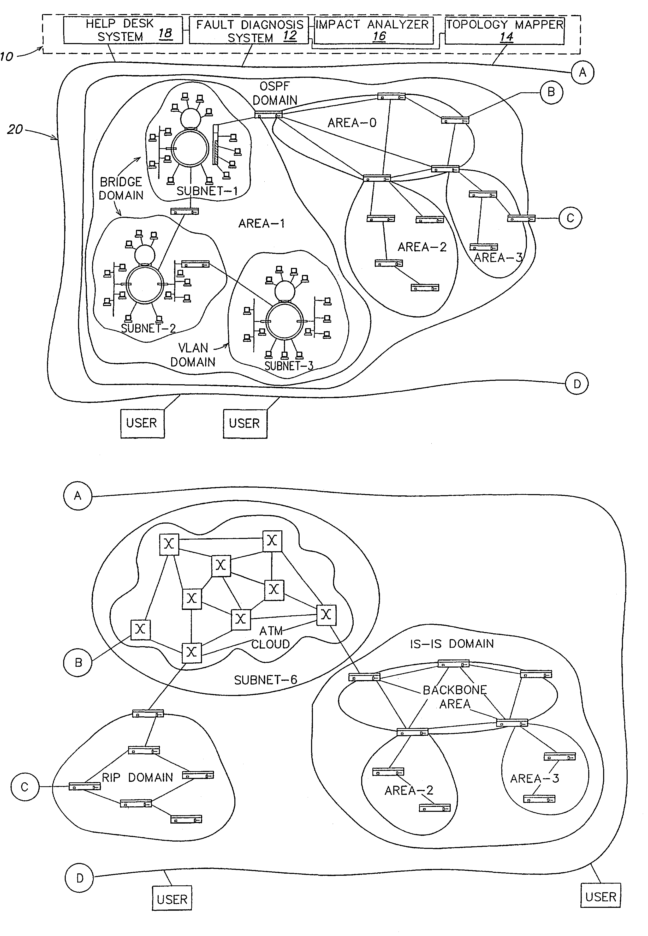
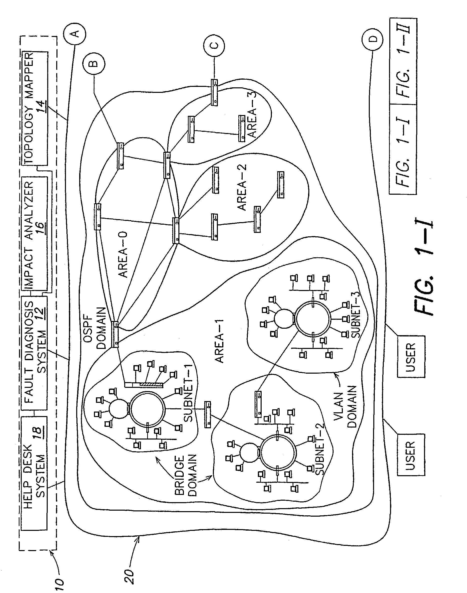
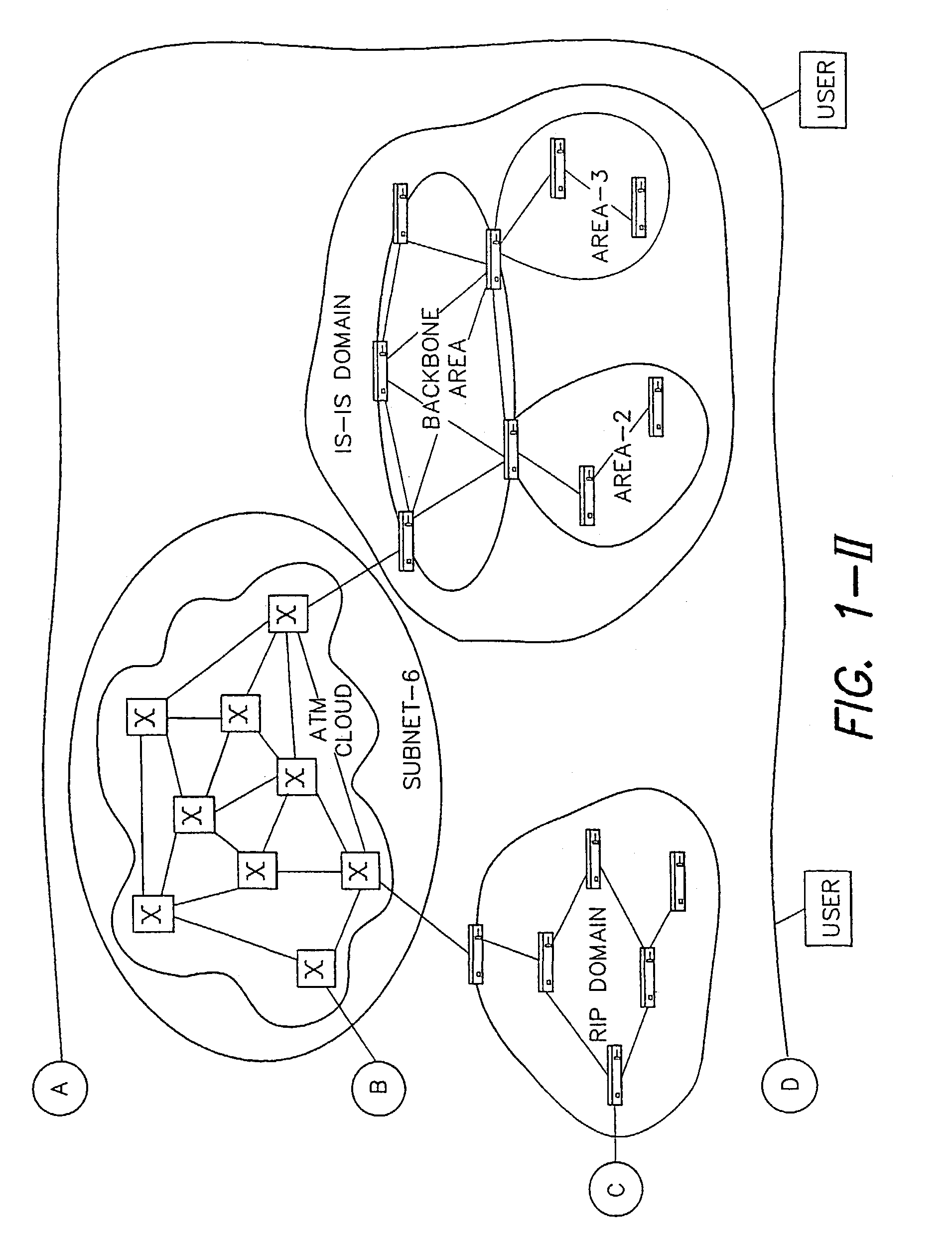
[0052]FIG. 1 shows diagrammatically a network management system 10 including a fault diagnosis system 12, a topology mapper 14, an impact analyzer 16 and a help desk system 18. The network management system communicates with a communications network 20 (or application service). The network includes a set of interconnected network elements such as routers, bridges, switches, and repeaters. These network elements provide transportation of data between end stations. Furthermore, there are computers known as servers that provide services such as e-mail, accounting software, sales tools, etc. Typically, data is transmitted electronically or optically, and network elements can forward data in packets, frames or cells to the intended destination. Servers include network adapters and / or software that interpret the electronic or optical data packet into the data elements and pass these elements to the appropriate application being hosted.

[0053]The network management system 10 includes a comm...


PUM


Abstract

A network management system (10) includes a fault diagnosis system (12) connectable to a communications network (20). The fault diagnosis system includes a fault object factory, a path determination module, and a fault diagnosis engine. The fault object factory is constructed and arranged to receive fault data and create fault objects. The path determination module is constructed to determine, in a communications network, a path related to the fault data. The fault diagnosis engine is constructed to perform, using the determined path, a fault analysis on the fault data to diagnose a fault related to the communications network. The network management may also include a help desk system (18), a topology mapper (14) or an impact analyzer (16).

Description

[0001]This application claims priority from a U.S. Provisional Application No. 60 / 202,296, entitled “Construction of a Very Rich, Multi-layer Topological Model of a Computer Network for Purposes of Fault Diagnosis,” filed on May 5, 2000, and claims priority from U.S. Provisional Application No. 60 / 202,299, entitled “A method for diagnosing faults in large multilayered environments guided by path and dependency analysis of the modeled system,” filed on May 5, 2000, and claims priority from U.S. Provisional Application No. 60 / 202,298, filed on May 5, 2000, entitled “Method and apparatus for performing integrated computer network, system, and application fault management,” all of which are incorporated by reference in their entireties.GENERAL DESCRIPTION[0002]The invention relates to detecting, diagnosing and managing faults in communications networks.[0003]The construction of computer networks started on a large scale in the 1970's. Computer networks link personal computers, workstati...

Claims


Application Information

Patent Timeline
IPC IPC(8): G06F11/00G06F11/25H02H3/05
CPCG06F11/2257
Inventor GREENWALD, JOSEPHBALL, SCOTTBUIA, CHRISTOPHERCARON, JONATHAN P.TAYLOR, DAVID K.
Owner COMP ASSOC THINK INC
Learn More