
CDMA communication system with pilot power control unit

a communication system and power control technology, applied in the field of radio communication systems, can solve the problems of increasing construction costs, burden, and inability to perform soft h/o functions unique to cdma communication, and achieve the effect of increasing the transmission power valu

Inactive Publication Date: 2007-06-26
NEC CORP
View PDF17 Cites 29 Cited by
  • Summary
  • Abstract
  • Description
  • Claims
  • Application Information

AI Technical Summary

Benefits of technology

[0035]The present invention is devised to solve the above problems without changing the cell design. The present invention therefore has an object to secure a satisfactory reception environment efficiently regardless of a degree of the traffic intensity. More concretely, the present invention has an object to secure the soft H / O function, which is one of the important characteristics of the CDMA communication method, throughout the areas even when the traffic intensity per cell is high.
[0036]The present invention has another object to provide a communication service with a satisfactory sound quality by avoiding the pilot pollution caused when the traffic intensity per cell is low and thereby preventing the system from becoming too tight.

Problems solved by technology

However, such a circular area is susceptible to geographical conditions, such as buildings, mountains, etc., in practice.
This causes problems as described below.
This raises a problem that the soft H / O function unique to the CDMA communication is not performed smoothly or cannot be performed at all.
On the other hand, Solving the above problem by the cell design would cause a problem as follows.
This cell design, however, requires a greater number of base stations, which increases the construction cost and imposes a burden.
This will become a problem in that the utilization of a radio channel is increased.
In the pilot pollution state, the soft H / O is performed so frequently that the sound quality is deteriorated.
Also, such frequent soft H / O causes a problem that the system becomes too tight.

Method used


Image

  • CDMA communication system with pilot power control unit
  • CDMA communication system with pilot power control unit
  • CDMA communication system with pilot power control unit

Examples


Embodiment Construction

[0055]The following description will describe a control method of the transmission power of a pilot signal in the CDMA communication method in accordance with one embodiment of the present invention. It should be appreciated, however, that the following embodiment is for illustrative purpose only, and the present is not limited thereto.

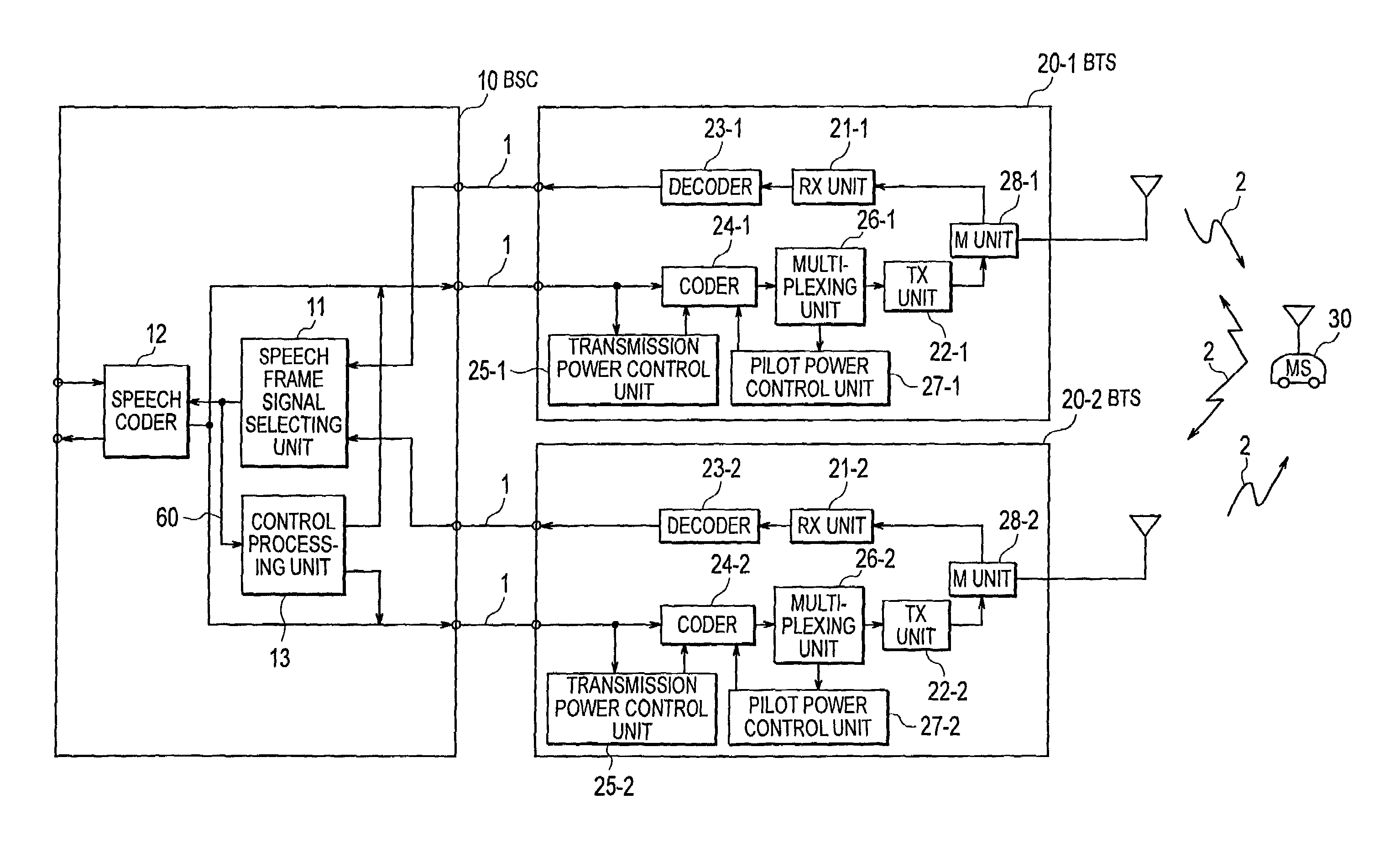
[0056]In the first place, with reference to FIGS. 7 and 8, explanation is given to an arrangement of a control system of the transmission power of a pilot signal in the CDMA communication method in accordance with one embodiment of the present invention.

[0057]FIG. 7 is a view showing an arrangement of the control system of the transmission power of a pilot signal in the CDMA communication method in accordance with one embodiment of the present invention.

[0058]As shown in the drawing, a BTS 20 comprises: an RX unit 21 for receiving and demodulating a radio signal 2; a decoder 23 for decoding the demodulated signal into a speech control frame signal 70;...


PUM


Abstract

A satisfactory reception environment is secured efficiently regardless of a degree of the traffic intensity. A pilot power control unit is provided to a base station radio unit. The pilot power control unit controls a desired wave power-to-interference wave power ratio of a pilot signal to stay at a preset value. More specifically, upon receipt of a multiplex wave from a multiplexing unit, the pilot power control unit computes a desired wave power-to-interference wave power ratio of a pilot signal. Then, the pilot power control unit transmits a command signal to a coder to change a transmission power value of the pilot signal in an amount corresponding to a difference between the computed desired wave power-to-interference wave power ratio and a set desired wave power-to-interference wave power ratio.

Description

BACKGROUND OF THE INVENTION[0001]The present invention relates to a radio communication system using the CDMA (Code Division Multiple Access) communication method abide by the IS-95 standard, and more particularly to control of the transmission power of a base station radio unit in a radio communication system.[0002]A method of connecting a plurality of mobile stations to a base station in the same frequency band is referred to as multiplex access or multiple access. With the CDMA (Code Division Multiple Access) communication method, multiple access is performed by the spread spectrum communication. The spread spectrum communication is a communication means for transmitting spectrum an information signal by spreading a spectrum thereof to a sufficiently wide bandwidth compared with the original information bandwidth.[0003]Each information signal is assigned with a spread code sequence orthogonal to each other. Each information signal is multiplied with the assigned spread code seque...

Claims


Application Information

Patent Timeline
IPC IPC(8): H04B7/216H04B7/005H04B7/26H04W52/04H04J13/00H04W52/24H04W52/32
CPCH04W52/143H04W52/241H04W52/246H04W52/32H04W52/325H04W52/50H04W52/40H04W52/24H04B7/26
Inventor KONO, MASAKI
Owner NEC CORP
Learn More