
Expandsible Receiver Module

Active Publication Date: 2007-06-05
SONION ROSKILDE
View PDF13 Cites 180 Cited by
  • Summary
  • Abstract
  • Description
  • Claims
  • Application Information

AI Technical Summary

Benefits of technology

[0032]The receiver module may further comprise a filter positioned in the opening of the expansible mean so as to cover the output port of the receiver housing. Alternatively, the receiver module may comprise a membrane positioned in the opening of the expansible mean so as to cover the output port of the receiver housing in order to protect the receiver against cerumen.
[0042]The receiver module may further comprise a vent canal, said vent canal forming part of the inflatable means and the tube section so as to establish an unbroken vent canal from the second end part of the tube section to a point adjacent to the opening of the inflatable means. This vent canal is used to avoid occlusion and to equalise pressure between the area between the receiver module and the eardrum, and the outside.
[0054]It may be advantageous to shape the expansible means in a way so that, in a cross-sectional profile, the expansible means takes an elliptically shaped profile.

Problems solved by technology

The reason for this being that the plastic material forming the shell encapsulating the above-mentioned components is hard, which makes it impossible to position a conventional hearing aid with a plastic shell in the bony area of the ear canal without introducing pain to the user of the hearing aid.
Another disadvantage of one-piece hearing aids is the large distance between the receiver output and the eardrum to be excited.
Other disadvantages relating to one-piece hearing aid are acoustic feedback from the receiver to the microphone, vibrations of the receiver, which is transmitted to the ear canal, unpleasant for the user and finally the rather complicated and painful mounting of the hearing aid.
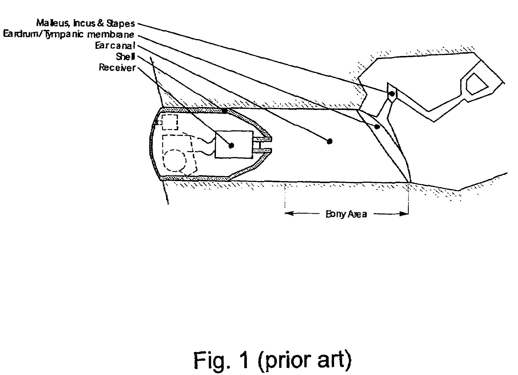
However, the balloon introduced in U.S. Pat. Nos. 6,094,494 and 4,133,984 does not solve the above-mentioned problems in that the hearing aid is still a one-piece device—the only difference compared to the hearing aid of FIG. 1 is that a flexible sound-leading portion has been attached to the hearing aid in order to guide sound from the receiver, which is still positioned at a large distance from the eardrum, to an opening near the inner end of the flexible sound-leading portion.
Thus, problems related to the large distance between the receiver output and the eardrum is not solved by the set-ups suggested in U.S. Pat. No. 6,094,494 and 4,133,984.
Even further, since the systems of U.S. Pat. No. 6,094,494 and 4,133,984 are still one-piece hearing aids problems such as acoustic feedback from the receiver to the microphone, vibrations of the receiver, which is transmitted to the ear canal, are still present and may easily influence the performance of the hearing aid in a negative direction.

Method used


Image

  • Expandsible Receiver Module
  • Expandsible Receiver Module
  • Expandsible Receiver Module

Examples


Embodiment Construction

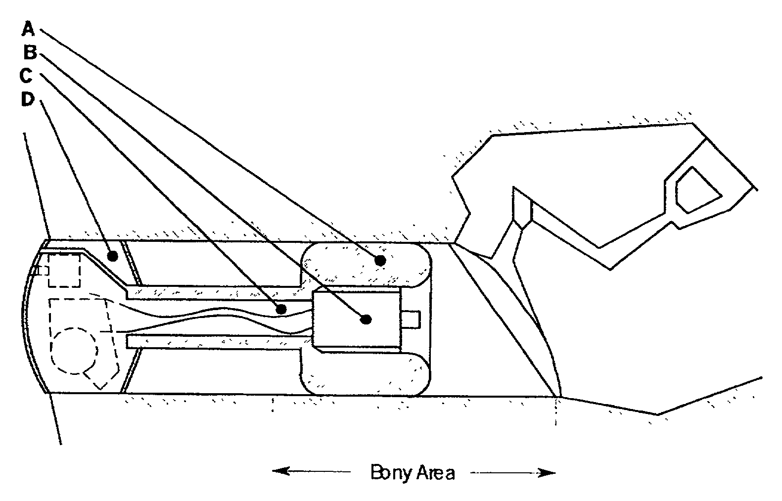
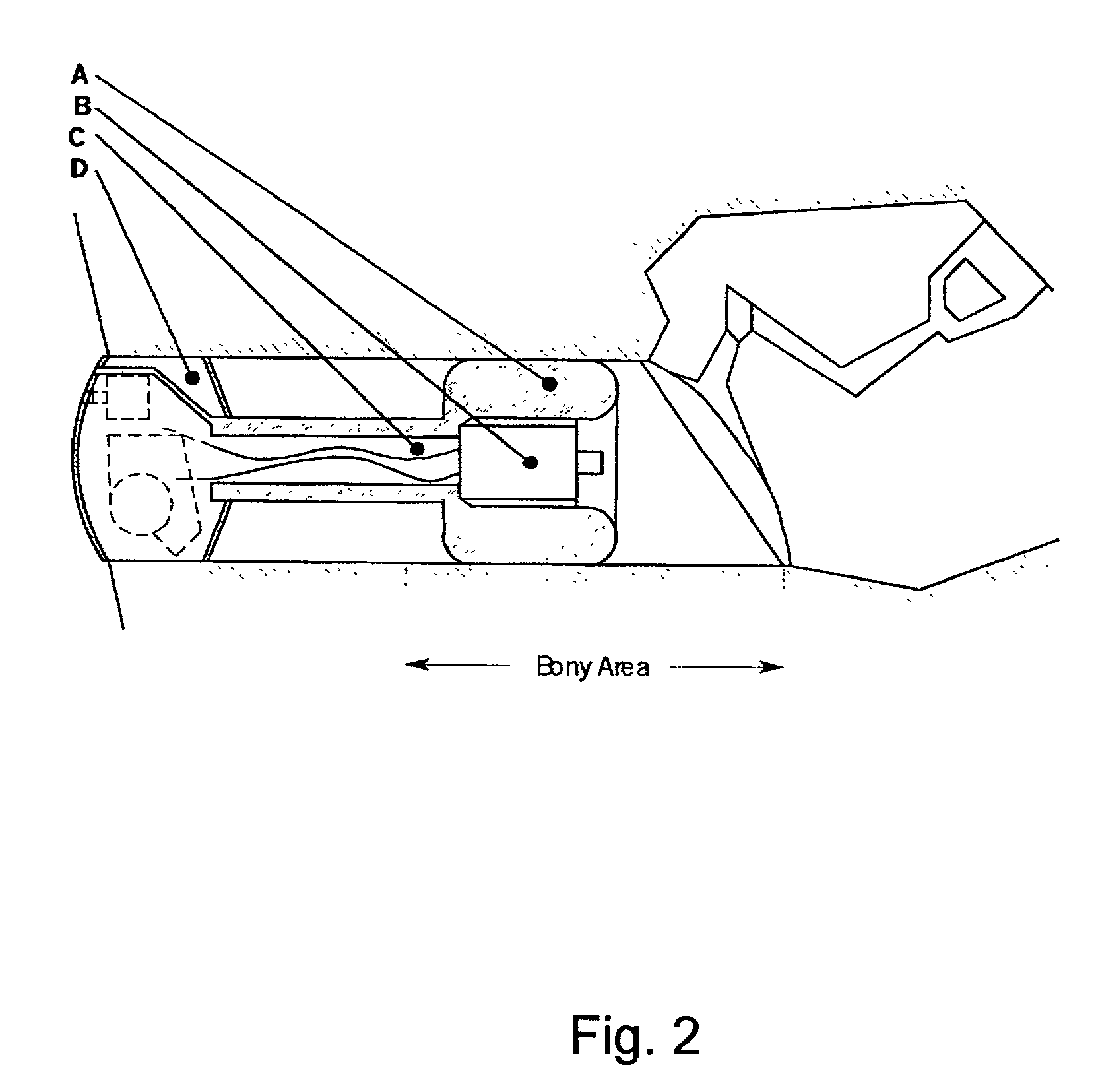
[0077]The main aspect of the present invention is illustrated in FIG. 2 where receiver B is at least partly surrounded by inflatable means A (e.g. balloon) which is connected to hearing aid D via tube section C. Inflatable medium A is connected to the outside and can be inflated using some kind of pump.

[0078]Inflatable means A could be a balloon which, after being inserted in the ear canal, is inflated with air, liquids, gel or the like. An external pump is used to inflate the balloon. Preferably, the pump may be controlled by the user so that the user may adjust the pressure in the balloon so as obtain maximum comfort.

[0079]In an alternative embodiment, the inflatable means can also be a flexible member filled with some sort of elastic foam. The dimensions / volume of this flexible member can be controlled by controlling the amount of air in the foam. For example, the volume of the flexible member can be reduced by pumping air out of the foam whereby the flexible member can be brough...


PUM


Abstract

The present invention relates to a receiver module being adapted to be positioned in an ear canal, the receiver module comprising a receiver having a receiver housing, said receiver being adapted to receive a time dependent electrical signal, said receiver further being adapted to generate outgoing acoustic waves via an output port in the receiver housing in response to the received time dependent electrical signal, and expansible means surrounding at least part of the receiver housing, said expansible means having an opening aligned with the output port of the receiver housing so as to allow the generated outgoing acoustic waves to penetrate away from the receiver module and into the ear canal.

Description

[0001]The present invention relates to expansible receiver modules. In particular, the present invention relates to expansible receiver modules for hearing aids. Such expansible receiver modules are suitable for being mounted within the bony area of the ear canal.BACKGROUND OF THE INVENTION[0002]Hearing aids today are typically manufactured in one piece—i.e. one component comprising all necessary sub-devices such as microphone, amplifier and receiver—the latter being used to generate a sound pressure so as to excite the eardrum in response to sound pressure captured by the microphone. The components—microphone, amplifier and receiver—are encapsulated in a common plastic shell as illustrated in FIG. 1.[0003]As seen in FIG. 1, the hearing aid is positioned at a relatively large distance from the eardrum—in front of the bony area of the ear canal. The reason for this being that the plastic material forming the shell encapsulating the above-mentioned components is hard, which makes it i...

Claims


Application Information

Patent Timeline
IPC IPC(8): H04R25/00
CPCH04R25/652H04R25/656H04R2460/11
Inventor VAN HALTEREN, AART ZEGERJORGENSEN, MARTIN BONDOVIDEB.AE BUTTED.K, KARSTENBROUWER, THEODORUS GERARDUS MARIASPAANDERMAN, PAULUS TEUNMOCKING, DENNIS JACOBUS MATTHEUSAUGUSTIJN, JEROEN PIETER JOHANNES
Owner SONION ROSKILDE
Learn More