
Rear loading roof top transporter

a rear loading and roof top technology, applied in the direction of vehicle components, other load carrying vehicles, supplementary fittings, etc., can solve the problems of many users, exerting a great deal of effort to utilize the roof rack, and a problem in accessing the roof rack

Inactive Publication Date: 2007-06-05
MAGNA INTERNATIONAL INC
View PDF38 Cites 58 Cited by
  • Summary
  • Abstract
  • Description
  • Claims
  • Application Information

AI Technical Summary

Problems solved by technology

Accessing the roof rack can, however, be a problem for many users.
Thus, an individual attempting to load a large or heavy item on the roof rack must exert a great deal of effort to utilize the roof rack.

Method used


Image

  • Rear loading roof top transporter
  • Rear loading roof top transporter
  • Rear loading roof top transporter

Examples


second embodiment

[0042]Referring to FIGS. 6 through 8, wherein like primed reference numerals represent similar elements as those described above, the invention includes a drive assembly, generally indicated at 96 in FIG. 7, for moving the tray 44′ between the storage and loading positions. The drive assembly 96 includes a motor 98, a clutch 100, and a gear 102.

[0043]The drive assembly 96 is housed within an interior portion 104 of a mounting panel 106. The interior portion 104 also houses electrical wiring 108 that extends from inside the motor vehicle 14′ to power the drive assembly 96. The mounting panel 106 is fixedly attached to the roof 12′ and extends between the pair of rails 26′, 28′. Although the drive assembly 96 is shown as being housed within the mounting panel 106, it is contemplated that the drive assembly 96 may be located at various positions outside of the mounting panel 106.

[0044]Still referring to FIG. 7, the mounting panel 106 extends between a pair of front stanchions 110 (one ...

third embodiment

[0058]It is appreciated that although the cover assembly 144 has been shown and described in relation to the invention, the cover assembly 144 is equally applicable to all of the other embodiments disclosed herein.

fourth embodiment

[0059]Referring to FIGS. 14 through 16, wherein like triple primed reference numerals represent similar elements as those described above, in the invention the drive mechanism is a belt 116″′ extending between a pair of pulleys 152, 154. The pulleys 152, 154 are disposed along the channel 36″′. One of the pair of pulleys 152 is positioned at the fore end 30″′ of one of the pair of rails 26″′, 28″′. The other of the pair of pulleys 154 is positioned at the aft end 32″′ of one of the pair of rails 26″′, 28″′, as is shown in FIG. 14. The pair of rails 26″′, 28″′ is shaped to accommodate the belt 116″′ and the sliding bracket 56″′ secured thereto.

[0060]Upon activation of the drive assembly 96″, the belt 116″ drives the sliding bracket 56′″ between the fore 30′″ and aft 32′″ ends of one of the pair of rails 26′″, 28′″ to move the tray 44′″ (not shown in FIGS. 14 through 16) between its storage and loading positions.


PUM


Abstract

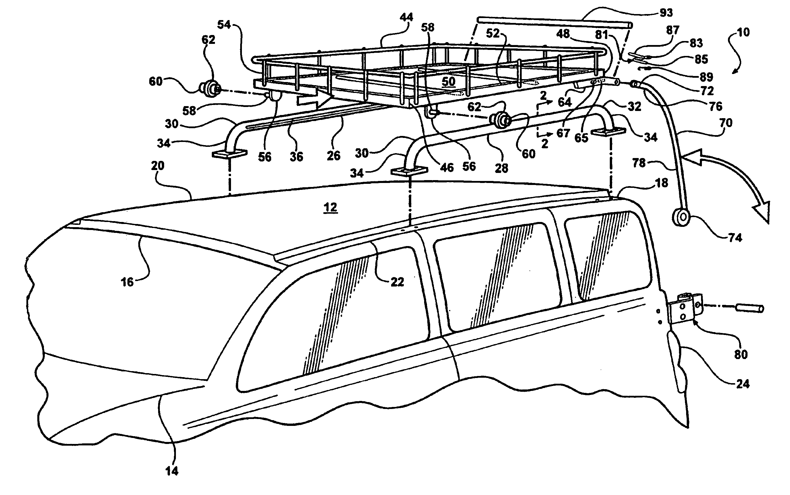
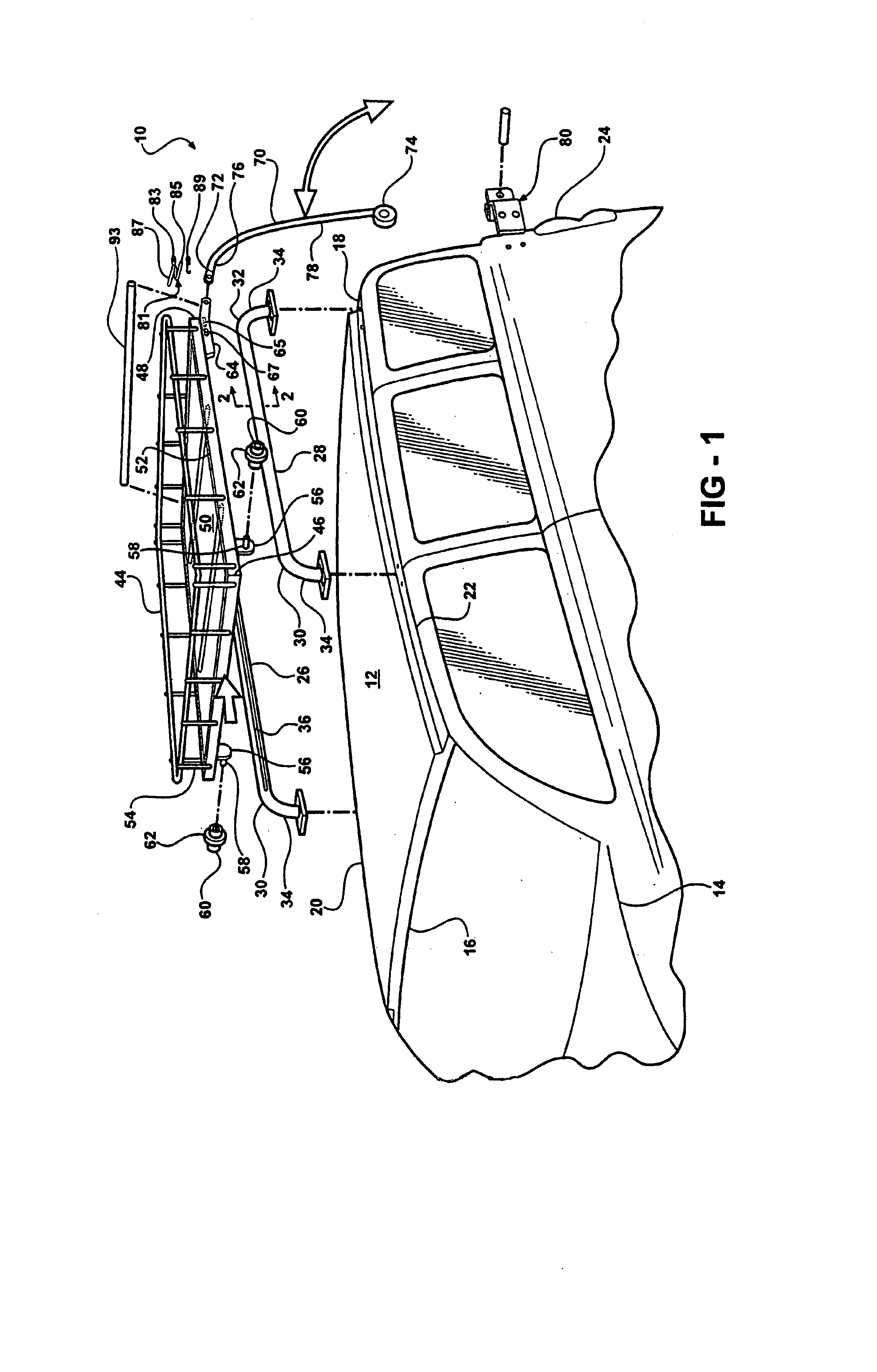
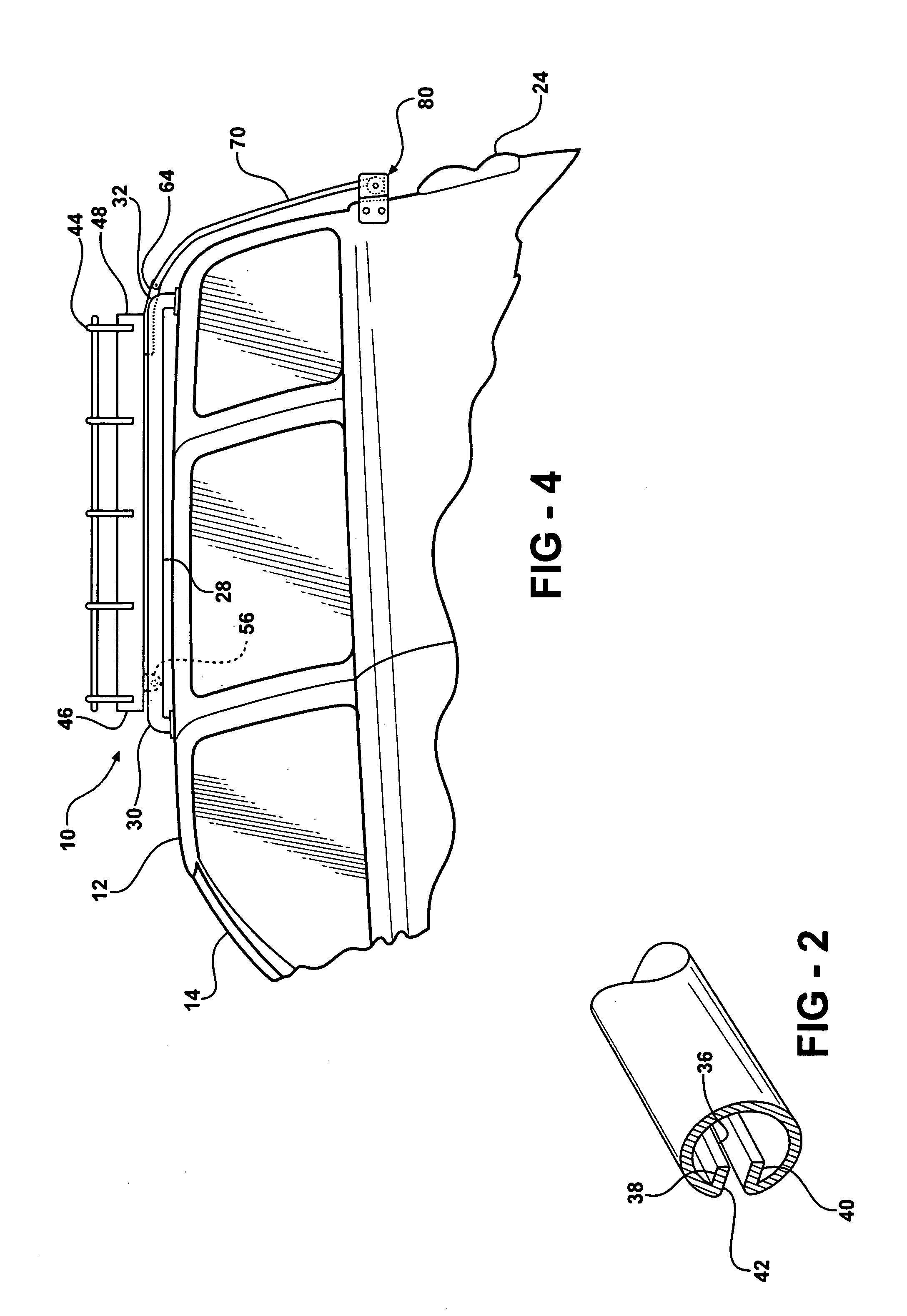
A roof rack assembly is provided for storing items above a roof of a motor vehicle. The roof rack assembly includes a pair of rails fixedly secured to the roof, parallel to each other. Each of the rails has a channel therealong. A tray includes a first end slidingly engaging the channel and a second end. The tray is movable between a storage position above the roof and a loading position along the side of the motor vehicle. A pair of pivot arms extends between a receiving end and a pivot end. The receiving end is pivotally coupled to the second end of the tray. A pair of mounting brackets are fixedly secured to the side of the motor vehicle and pivotally coupled to the pivot arms at the pivot end thereof. Each of the mounting brackets includes a stop for limiting pivotal movement of the pivot arms as the tray moves from the storage position to the loading position in order to maintain the tray in the loading position.

Description

FIELD OF THE INVENTION[0001]This invention relates to a roof rack assembly for a motor vehicle. More particularly, the invention relates to a roof rack assembly that is movable between storage and loading positions.DESCRIPTION OF THE RELATED ART[0002]Roof racks allow for the storage of various items, including luggage, trunks, bicycles, canoes, and skis, above a roof of a motor vehicle. The storage of such items above the roof increases storage capacity of the motor vehicle.[0003]Accessing the roof rack can, however, be a problem for many users. For example, sport utility vehicles and minivans typically have a roof height above the shoulder level of most individuals. As a result, any item that is to be stored on the roof rack must first be raised above the roof height before loading onto the roof rack. In addition, once the item is raised to the roof, it may need to be tied to the roof rack in order to remain thereon during motor vehicle operation. Thus, an individual attempting to ...

Claims


Application Information

Patent Timeline
Patent Type & Authority Patents(United States)
IPC IPC(8): B60P9/00B60R9/042
CPCB60R9/042
Inventor HENDERSON, JACK V.TURNEY, CHARLES
Owner MAGNA INTERNATIONAL INC
Learn More