
Operation lamp with camera system for 3D referencing

a technology of 3d referencing and operation lamp, which is applied in the field of refractive referencing system, can solve the problems of compromising referencing accuracy, unable to accurately referencing, and difficult to suitably position and align the camera, so as to achieve the effect of convenient operation and adjustmen

Active Publication Date: 2007-05-29
BRAINLAB
View PDF26 Cites 37 Cited by
  • Summary
  • Abstract
  • Description
  • Claims
  • Application Information

AI Technical Summary

Benefits of technology

[0006]The present invention provides a system for referencing three-dimensional spatial co-ordinates, in particular of surgical or medical instruments, which is even easier to operate and adjust.

Problems solved by technology

In certain situations, this can be difficult.
Suitably positioning and aligning the cameras is thus comparatively difficult.
It can nonetheless easily transpire that the field of view of one or more may be obscured at the same time, making accurate referencing impossible.
Positioning the cameras at a comparatively long distance from the relevant area in which three-dimensional spatial co-ordinates are to be detected also has the disadvantage that a comparatively large amount of zero order information is detected by the cameras, which can compromise the referencing accuracy, or at least unnecessarily increases the computational demands involved.

Method used


Image

  • Operation lamp with camera system for 3D referencing
  • Operation lamp with camera system for 3D referencing
  • Operation lamp with camera system for 3D referencing

Examples


first embodiment

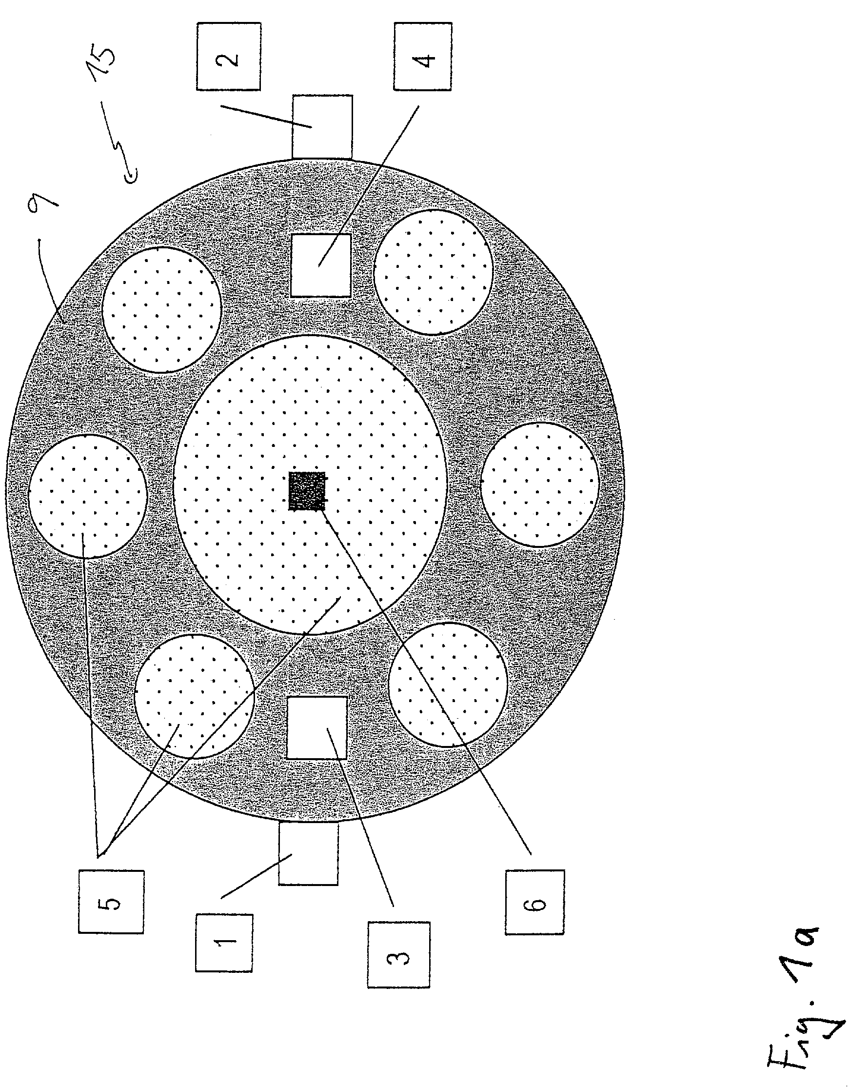
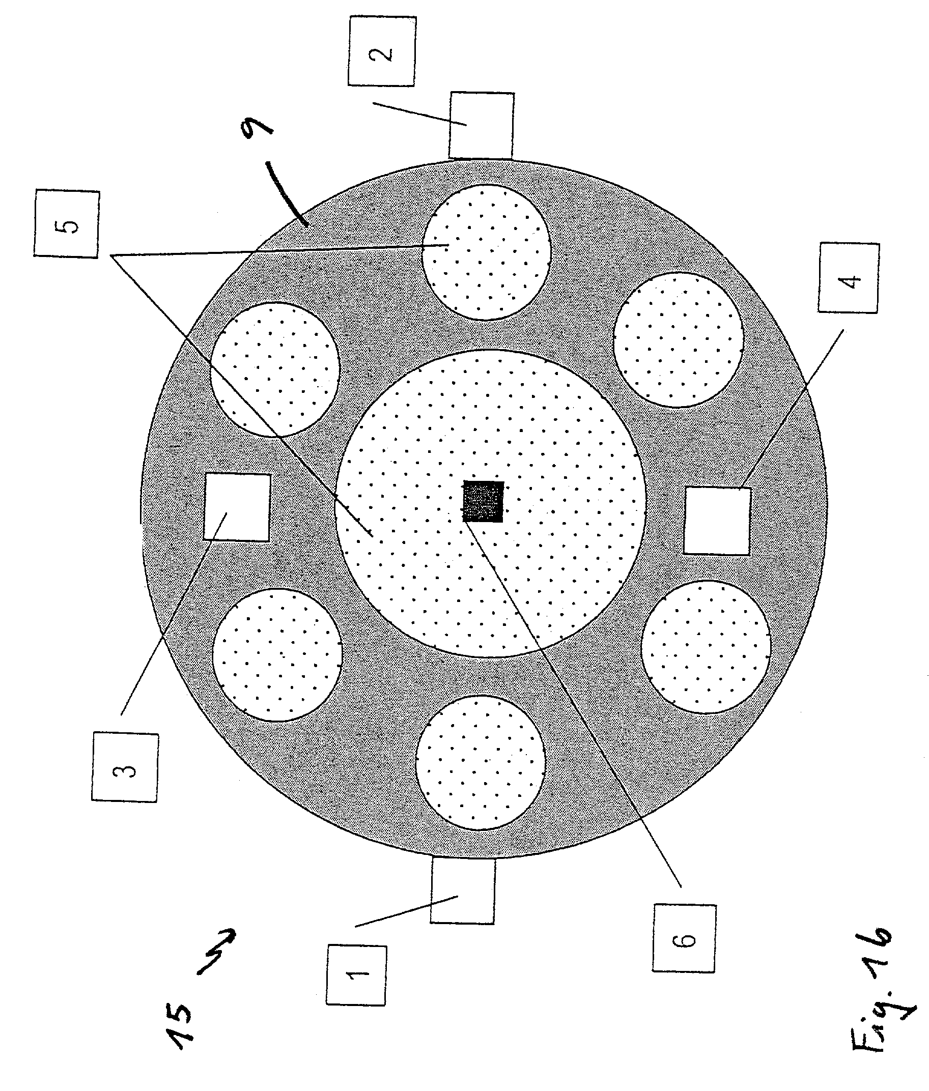
[0030]FIGS. 1 and 2 show a schematic underside view and a cross-section of a system in accordance with the present invention. The system comprises the light source 15 and four cameras 1 to 4, which serve to reference three-dimensional spatial co-ordinates in accordance with the optical navigation method described in DE 196 39 615 C2. To this end, the signals detected by the cameras 1 to 4 are transmitted to a subordinated computational unit (not shown). The light source 15 has a circular cross-section and comprises a central illuminating means 5 and six illuminating means 5 arranged point-symmetrically to it, each held in the casing 9. The illuminating means 5 provide an area A with substantially shadow-free illumination. To this end, the illuminating means 5 can emit the light substantially vertically from the plane spanned by the base of the casing 9, or they can be inclined at an angle, as is known to the person skilled in the art in this field. Conventionally, the light source 1...

second embodiment

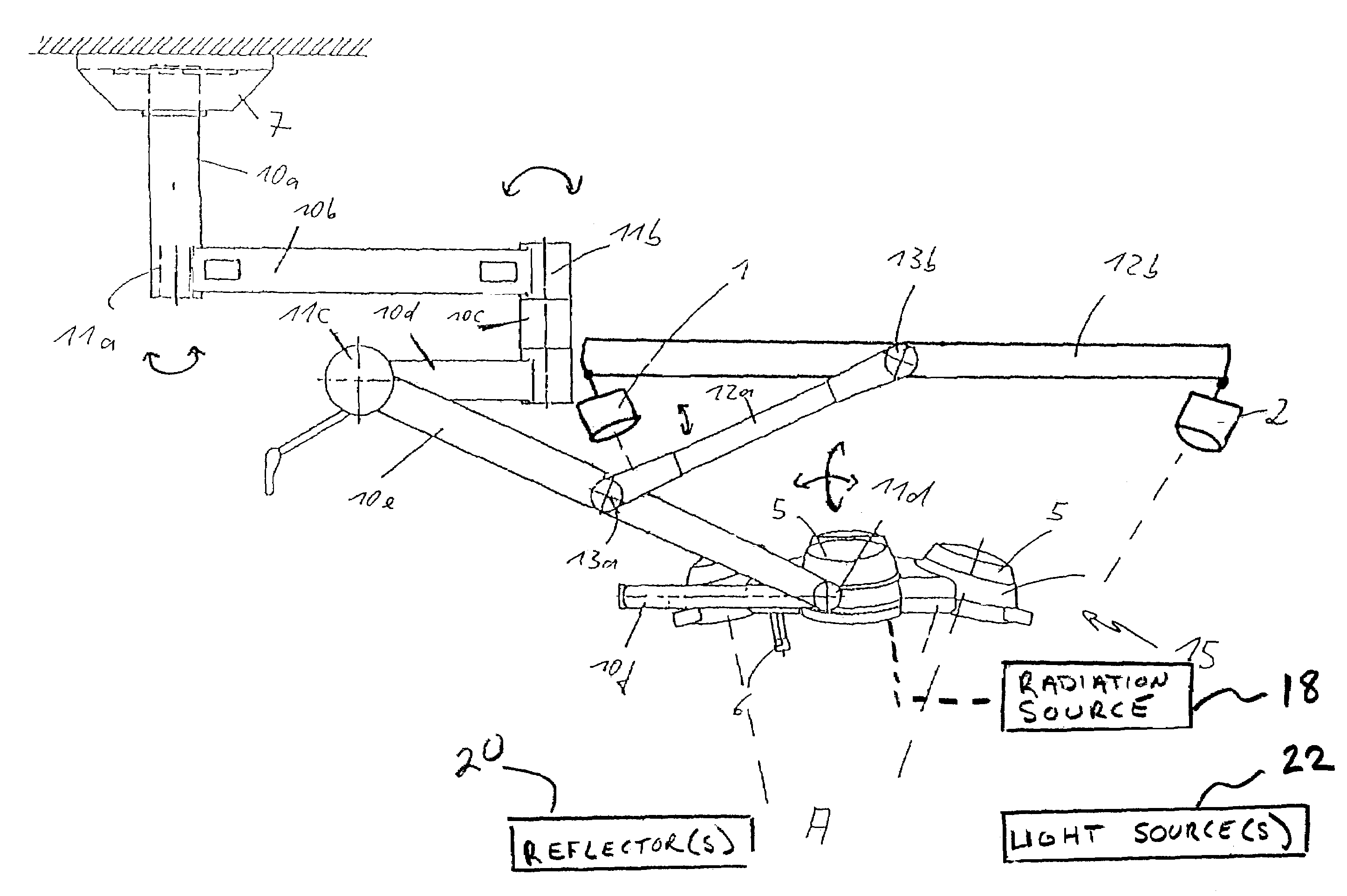
[0040]FIG. 3 shows a schematic side view of the system in accordance with the invention. This system comprises the light source 15 and the cameras 1, 2 which are suspended together from the ceiling by a supporting arm construction. The supporting arm construction comprises a number of arms 10a–f extending from the ceiling attachment 7 and which can be axially rotated at the joints 11a, 11b and pivoted perpendicular to the second plane in FIG. 3 in the joint areas 11c and 11b, such that within the range of the arms 10a–f, the light source 15 can be positioned and orientated in almost any way with respect to an object which is to be illuminated. The light source 15 itself comprises three illuminating means 5 which illuminate the area A in star-shaped, point-symmetrical arrangement. The cameras 1, 2 are held by the common arm 12a, 12b of the camera suspension 12a, 12b. The arms 12a, 12b can be pivoted about the joints 13a, 13b, perpendicular to the drawing plane in FIG. 3, as shown. In...


PUM


Abstract

The invention relates to a system for the combined shadow-free illumination of a pre-definable area and for referencing three-dimensional spatial co-ordinates, and to an active or passive referencing system, each in particular for referencing surgical or medical instruments. The system is characterized in that at least two cameras and the light source (operation lamp) are held together such that the optical signals detected by the cameras, for referencing three-dimensional spatial co-ordinates in the area illuminated by the light source, can be evaluated. Since the field of view of the light source, in its conventional use, is not obscured or only negligibly obscured, this field of view can simultaneously be used for optical navigation by the cameras held together with the light source. In accordance with the invention, the cameras are automatically aligned optimally for optical navigation.The cameras can be rigidly or flexibly connected to the light source. The position and / or orientation of the cameras can be adjustable.

Description

FIELD OF THE INVENTION[0001]The present invention relates to a system for the combined, shadow-free illumination of a pre-definable area and for referencing three-dimensional spatial co-ordinates, in particular of surgical or medical instruments, and to a reflector referencing system.BACKGROUND OF THE INVENTION[0002]Referencing systems in the sense of this application are known for example from DE 196 39 615 C2, the content of the disclosure of which is explicitly incorporated by way of reference in the present application. Such systems, also known as navigation systems, provide the connection between the surgeon carrying out the treatment, i.e. the patient anatomy as the surgeon sees it during treatment, and diagnostic data obtained for example from computer tomography and represented visually by an image output via a computational unit. For detecting three-dimensional spatial co-ordinates, a plurality of markers with known dimensions are used, such as are for example described in ...

Claims


Application Information

Patent Timeline
IPC IPC(8): G01B11/24A61B1/06A61B5/05G01B11/14G01B11/30A61B19/00F21S8/00G01B11/03
CPCA61B19/5202A61B2019/5255F21W2131/205Y10S362/804A61B2034/2055A61B90/30
Inventor BAUCH, THOMASVILSMEIER, STEFAN
Owner BRAINLAB
Learn More