
Blood aspiration system and methods of use

a technology of blood aspiration and aspiration tube, which is applied in the field of blood aspiration tube, can solve the problems of high opportunity for embolic material to be released, ischemia may pose a serious threat to the health or life of patients, and it is difficult to establish the proper

Inactive Publication Date: 2007-05-29
WL GORE & ASSOC INC
View PDF25 Cites 202 Cited by
  • Summary
  • Abstract
  • Description
  • Claims
  • Application Information

AI Technical Summary

Benefits of technology

[0012]In view of the foregoing, it is an object of the present invention to provide a blood aspiration system that allows a catheter to achieve a substantially continuous rate of natural, physiologically-regulated aspiration through a working lumen of the catheter.
[0013]It is also an object of the present invention to provide a blood aspiration system that provides an appropriate rate of retrograde flow at a treatment site to direct dislodged particles into a catheter for efficient removal, without damaging the treatment vessel.
[0014]It is a further object of the present invention to provide a blood aspiration system having an easy to use pump that selectively may be used, in conjunction with natural aspiration techniques, to further influence flow in a treatment vessel.
[0016]It is yet a further object of the present invention to provide a blood aspiration system that allows emboli to be filtered and blood reperfused into a patient's vessel to reduce blood loss.
[0017]These and other objects of the present invention are accomplished by providing a blood aspiration system that is configured to enable three types of aspiration through a working lumen of a catheter. The blood aspiration system enables a substantially continuous rate of natural, physiologically-regulated aspiration through the working lumen using an arterial-venous shunt and, optionally, pump-assisted or suction-assisted aspiration through the catheter lumen. This allows a physician to provide a substantially continuous rate of retrograde flow in a treatment vessel during a medical procedure, while allowing a physician to further influence the rate of aspiration within the vessel.
[0019]In operation, the outlet port preferably is coupled to a venous return sheath, which is adapted to be disposed in a remote vein. When the venous return sheath is disposed in the remote vein, and when an occlusive element of the catheter is deployed in a patient's artery, a pressure differential between venous and arterial pressure will cause blood to flow in a retrograde fashion in the artery. This natural, physiologically-regulated aspiration through the manifold preferably occurs before, during and after a medical procedure performed through the working lumen of the catheter to effectively remove thrombi and / or emboli from the vessel.

Problems solved by technology

Generally during these procedures there is a high opportunity for the release of embolic material.
The emboli may travel downstream from the occlusion, lodging deep within the vascular bed and causing ischemia.
The resulting ischemia may pose a serious threat to the health or life of a patient if the blockage forms in a critical area, such as the heart, lungs, or brain.
However, several disadvantages arise when using an external suction system as the sole means for flow management within a vessel.
First, it may be difficult to establish the proper aspirating pressure required at the treatment site, and external pressure adjustments used with suction pumps may lead to an incorrect amount of suction for a given set of circumstances.
If the amount of suction is too low for the circumstances, then embolic particles may not be effectively removed and may travel downstream from the original occlusion, leading to further occlusive events.
If the amount of suction is too high, the vessel may collapse.
Moreover, if an external suction pump is utilized, retrieval of downstream emboli may require a flow rate that cannot be sustained by the vessel wall for more than a few seconds, resulting in insufficient removal of emboli.
Additionally, continuous use of an external suction pump may result in excessive blood loss, requiring infusion of non-autologous blood and raising related safety issues.
This cumbersome technique may cause injury to blood cells and may limit the ability of the physician while performing the procedure.
However, such natural aspiration techniques may provide insufficient flow to effectively remove emboli.

Method used


Image

  • Blood aspiration system and methods of use
  • Blood aspiration system and methods of use
  • Blood aspiration system and methods of use

Examples


Embodiment Construction

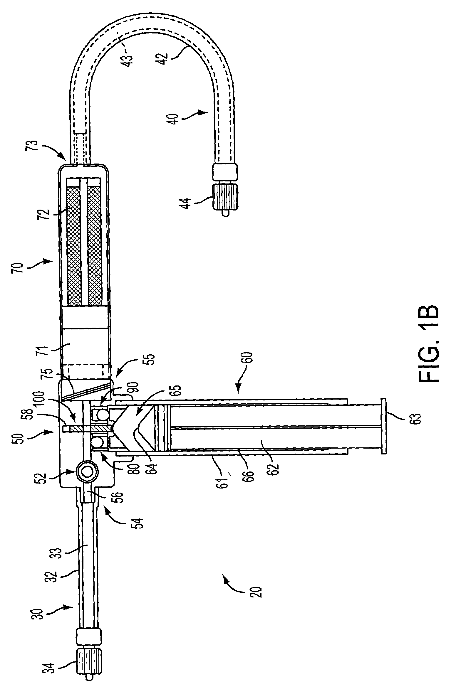
[0032]The present invention is directed to a blood aspiration system that is configured to enable natural aspiration through a working lumen of a catheter and, optionally, pump-assisted aspiration through the working lumen. The blood aspiration system enables a substantially continuous rate of natural, physiologically-regulated aspiration through the working lumen by enabling fluid communication between the working lumen and a patient's venous vasculature. The blood aspiration system further comprises a manually actuated pump provided to allow increased rates of aspiration through the working lumen. The provision of substantially continuous retrograde flow and, optionally, selectively increased rates of retrograde flow at a treatment site facilitates removal of emboli during an interventional procedure while minimizing trauma to the treatment vessel.

[0033]Referring now to FIG. 1, features of a blood aspiration system constructed in accordance with principles of the present invention...


PUM


Abstract

The present invention is directed to a blood aspiration system that is configured to enable various types of aspiration through a working lumen of a catheter. The blood aspiration system facilitates natural aspiration by providing a circuit between a patient's arterial and venous vasculature, and also comprises a manually actuated pump configured to selectively vary rates of aspiration in the working lumen. The blood aspiration system further comprises an external port that allows suction-assisted aspiration or infusion through the working lumen, and further comprises a detachable filter that removes emboli prior to reperfusing blood into a patient's venous vasculature.

Description

FIELD OF THE INVENTION[0001]The present invention relates to a blood aspiration system for use in conjunction with a catheter during a medical procedure, and more specifically, a system that is configured to provide a working lumen of the catheter with substantially continuous natural aspiration and, optionally, pump-assisted aspiration.BACKGROUND OF THE INVENTION[0002]Today there is a growing need to provide controlled access and vessel management during such procedures as stenting, atherectomy or angioplasty. Generally during these procedures there is a high opportunity for the release of embolic material. The emboli may travel downstream from the occlusion, lodging deep within the vascular bed and causing ischemia. The resulting ischemia may pose a serious threat to the health or life of a patient if the blockage forms in a critical area, such as the heart, lungs, or brain.[0003]Several previously known methods and apparatus incorporate the use of an external suction system in co...

Claims


Application Information

Patent Timeline
Patent Type & Authority Patents(United States)
IPC IPC(8): A61M37/00A61M5/00A61M1/00A61M29/00A61B17/22A61M25/00
CPCA61B17/22A61M1/0066A61M1/3621A61M25/00A61M1/0068A61M2202/0413A61M2202/06A61M2205/7545A61M2025/1052A61M1/3613A61M1/81A61M1/80
Inventor HOGENDIJK, MICHAEL
Owner WL GORE & ASSOC INC
Learn More