


Quick Research
Generate reliable direction feasibility study reports for your R&D in just a few steps.

Technical Q&A
Discover and master advanced knowledge NOW. Basics, ideas, possibilities, all at once.

Find Solutions
As an expert in R&D theories, this can generate solutions to your technical problems instantly.

Evaluate Feasibility
Analyze your overall solution with one click, know your potential R&D risks in advance.

Monitor Landscape
Get weekly tech updates, stay abreast of the latest tech innovations and key insights.
Ophthalmologic apparatus
a technology of ophthalmologic equipment and eye examination, which is applied in the field of ophthalmologic equipment, can solve the problems of deteriorating difficulty in examining a person to distinguish an index, and lengthening the time period required for eye examination, so as to improve the reliability of eye examination, shorten the time period of eye examination, and eliminate the confusion of a person
- Summary
- Abstract
- Description
- Claims
- Application Information
AI Technical Summary
Benefits of technology
Problems solved by technology
Method used
Image

Examples
first embodiment
[0030
[0031][Entire Structure]
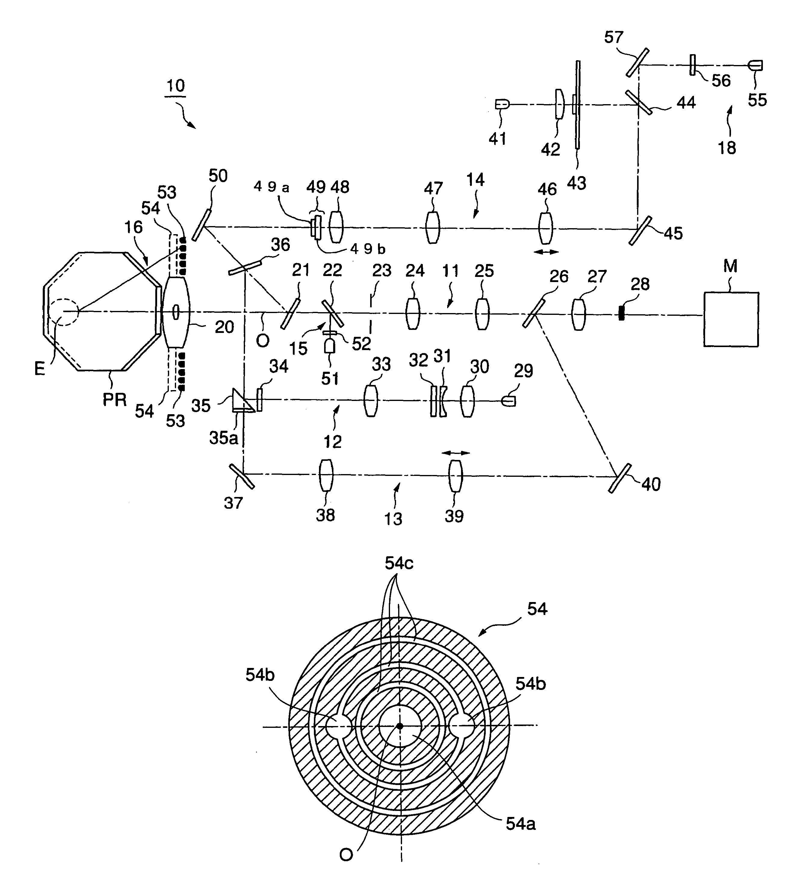
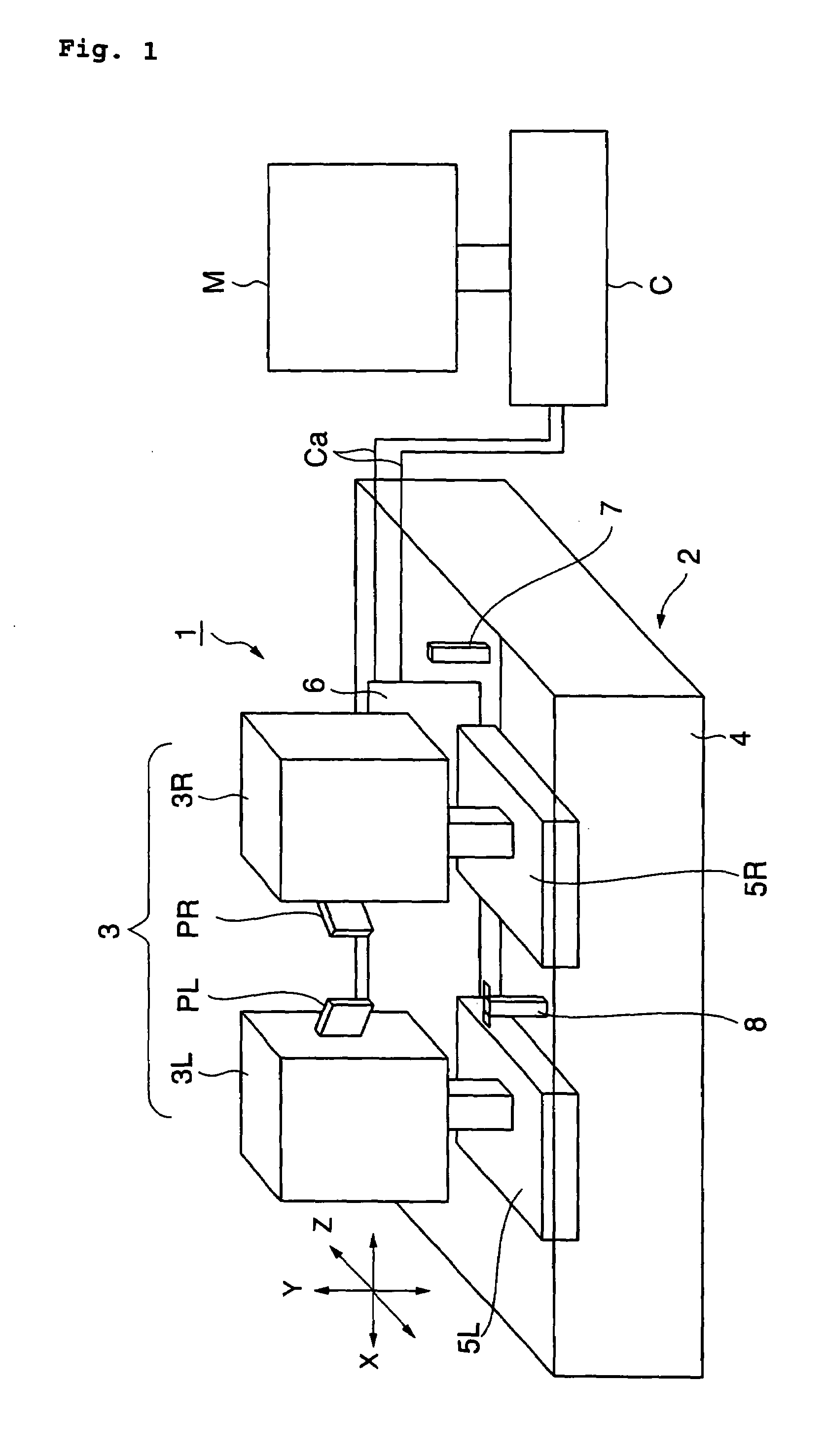
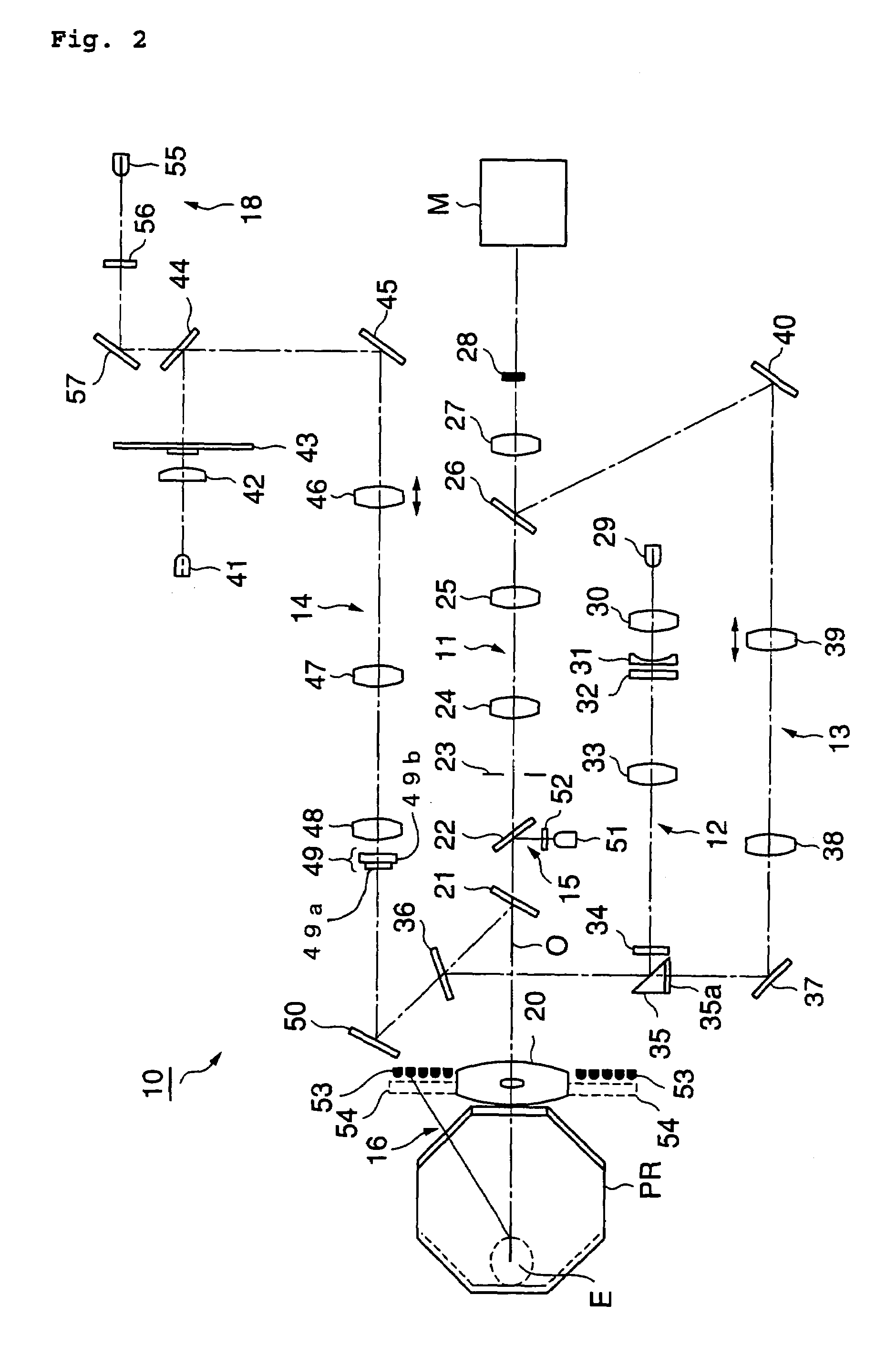
[0032]FIG. 1 is a perspective view showing an entire structure of an ophthalmologic apparatus 1 according a first embodiment of the present invention. The ophthalmologic apparatus 1 is an apparatus capable of conducting an astigmatic examination in addition to subjective and objective refractive power measurements in a situation in which an eye examination is conducted on a person to be examined alone or on a plurality of persons to be examined accompanied by an assistant who guides the plurality of persons to be examined. The eye examination is automatically conducted by the ophthalmologic apparatus 1 in accordance with predetermined processes. First, an approximate value of the refractive power of an eye to be examined is obtained by the objective refractive power measurement and the subjective measurement is conducted based on the obtained approximate value. Subsequently, astigmatic power and the like are obtained by conducting an astigmatic examinati...
second embodiment
[0081
[0082]Hereinafter, a second embodiment of the present invention will be described with reference to FIGS. 11A and 11B. FIGS. 11A and 11B show an identifier displaying member 60 which is used instead of the liquid crystal screen 56 of the ophthalmologic apparatus 1. FIG. 11A is a perspective view showing a schematic structure in the case where the identifier displaying member 60 is viewed from the front side and FIG. 11B is a side view showing the schematic structure of the identifier displaying member 60. Note that FIG. 11B shows a state in which the liquid crystal screen 56 of the ophthalmologic apparatus 1 is replaced by the identifier displaying member 60. The lamp 55 and the identifier displaying member 60 compose the identification information generating means.
[0083]As shown in FIGS. 11A and 11B, the identifier displaying member 60 includes an identification index plate 61 that displays an identifier “1”61a and an identifier “2”61b and a shutter 62 for shielding a region o...
third embodiment
[0088
[0089]A purpose of the third embodiment of the present invention as described below is to improve the identifying power for the index by simultaneously projecting a fusion frame to which a color is provided and the index. The fusion frame is an index for promoting a fusion of index images respectively recognized by the left eye EL and the right eye ER in the case where the index is simultaneously projected to both eyes of the person to be examined to conduct an eye examination. Note that an ophthalmologic apparatus according to this embodiment has substantially the same structure as the first embodiment described above. Therefore, only the feature section (identifier generating optical system) will be described here.
[0090]As described above, the left eye head 3L and the right eye head 3R each include the identifier generating optical system 18. In this embodiment, a multi-color LED that conducts switching light emission using, for example, red light and green light is disposed ...
PUM
 Abstract
Description
Claims
Application Information
 - R&D Engineer
- R&D Manager
- IP Professional
- Industry Leading Data Capabilities
- Powerful AI technology
- Patent DNA Extraction
Browse by: Latest US Patents, China's latest patents, Technical Efficacy Thesaurus, Application Domain, Technology Topic, Popular Technical Reports.
© 2024 PatSnap. All rights reserved.Legal|Privacy policy|Modern Slavery Act Transparency Statement|Sitemap|About US| Contact US: help@patsnap.com