
Installation assemblies for pipeline liners, pipeline liners and methods for installing the same

a technology for installing assemblies and pipelines, applied in the direction of pipe/joints/fittings, mechanical equipment, other medical devices, etc., can solve the problems of difficult access to a particular pipeline location, material thickness increase when the diameter of the expansion is larger, and the method of installing pipeline liners is difficult. achieve the effect of high integrity linings

Inactive Publication Date: 2007-05-15
NU FLOW TECH 2000
View PDF40 Cites 24 Cited by
  • Summary
  • Abstract
  • Description
  • Claims
  • Application Information

AI Technical Summary

Benefits of technology

[0039]The present invention provides advantages in that liners can be installed in pipelines in a relatively simple manner without requiring excavation to access the pipelines. The present invention also provides advantages in that liners can be installed at junctions between main and lateral pipes in a single application. The present invention provides further advantages in that variable diameter pipelines can be repaired and / or reinforced while ensuring high integrity linings.

Problems solved by technology

There are many disadvantages associated with current methods of installing pipeline liners.
Gaining access to a particular pipeline location can be difficult.
Although, expandable pipeline liner materials that accommodate the varying diameter of a pipeline are currently available, these materials become thinner when they expand to larger diameters.
As a result larger diameter sections of pipelines end up with a sub standard repair because there is not enough pipeline liner material to give it strength.
Another difficult area of pipelines to repair or re-enforce is the T-junction between a main pipe to a lateral line.
Current pipeline liners for T-junctions are difficult to install and require multiple steps, thus making the installation procedure time consuming for technicians.

Method used


Image

  • Installation assemblies for pipeline liners, pipeline liners and methods for installing the same
  • Installation assemblies for pipeline liners, pipeline liners and methods for installing the same
  • Installation assemblies for pipeline liners, pipeline liners and methods for installing the same

Examples


Embodiment Construction

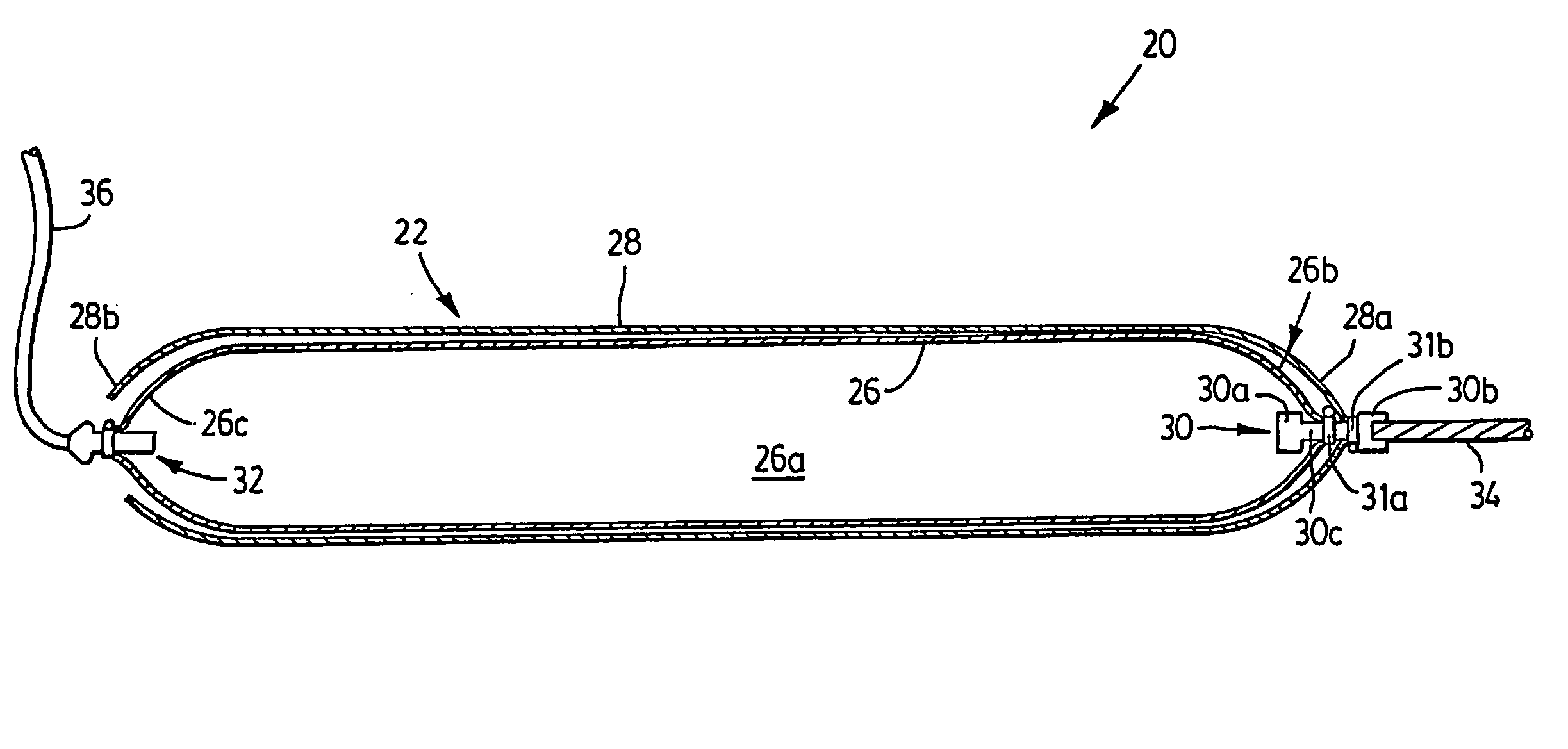
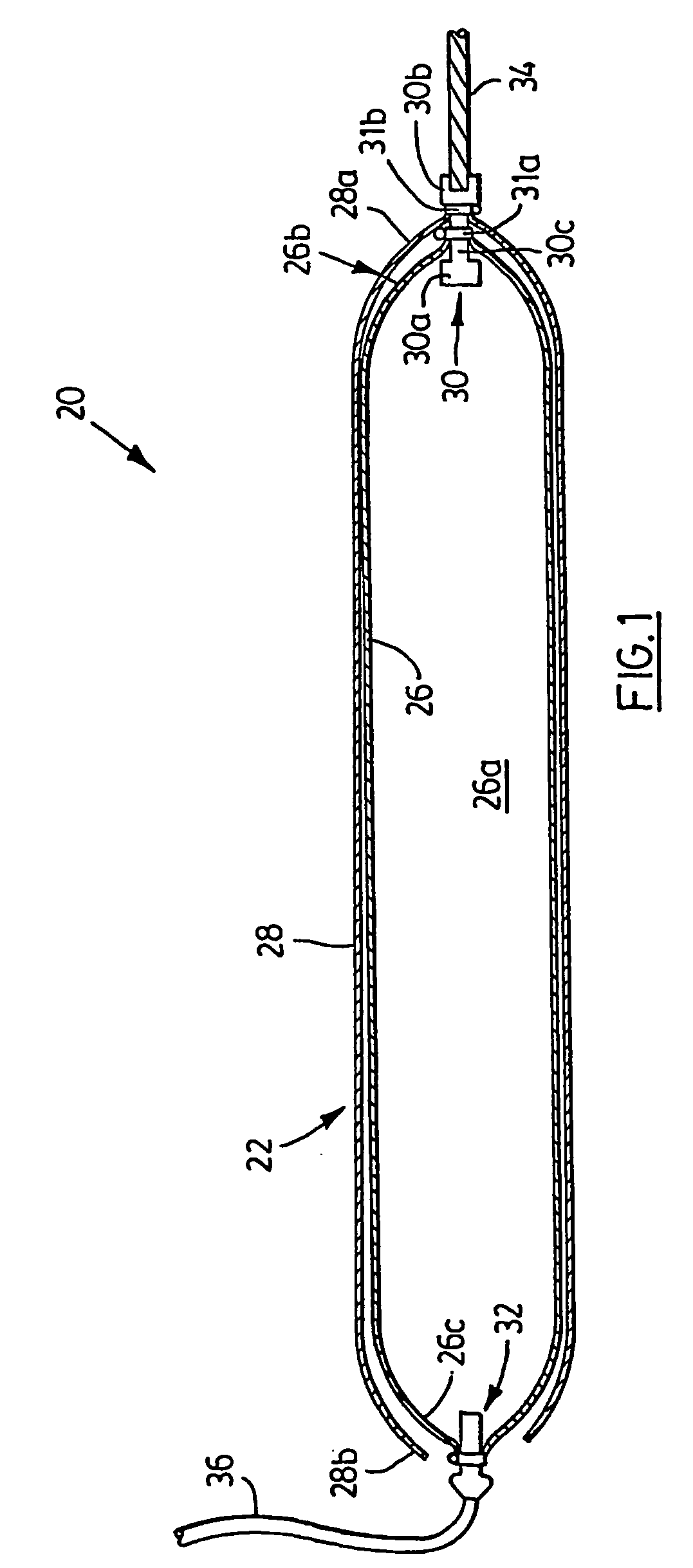
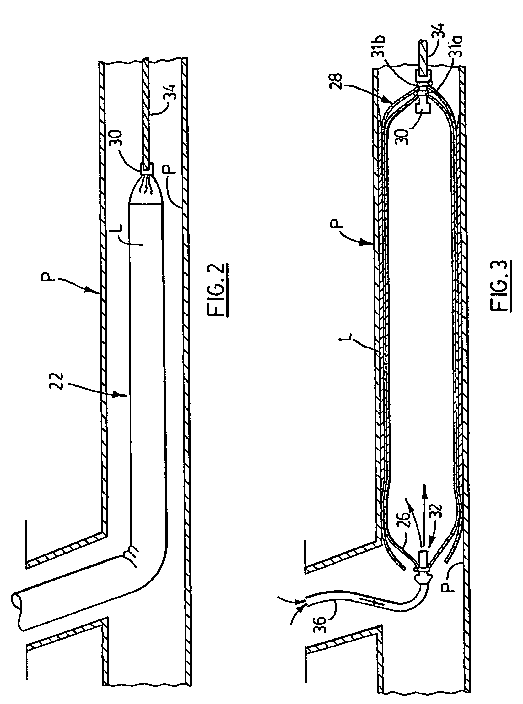
[0059]Turning now to FIG. 1, an installation assembly for installing a liner within a pipeline in accordance with the present invention is shown and is generally identified by reference numeral 20. As can be seen, installation assembly 20 includes a double bladder assembly 22 comprising an inner bladder 26 defining an internal reservoir 26a and an outer bladder 28 surrounding the inner bladder 26. The inner bladder 26 is elongate and has a leading installation end 26b and a trailing retrieval end 26c. An inversion element 30 that is generally shaped like an I-section having a pair of blocks 30a and 30b joined by a bight 30c, is partially accommodated by the inner bladder 26. Specifically, the leading installation end 26b of the inner bladder 26 receives the block 30a and is secured to the bight 30c by a clamp 31a to seal the leading installation end 26b of the inner bladder. The trailing retrieval end 26c of the inner bladder accommodates a valve 32 to enable fluid to enter the inte...


PUM


Abstract

An installation assembly (20) for installing a liner (L) in a pipeline (P) comprises a double bladder assembly (22) including an inner bladder (26) having an installation end (26b) and a retrieval end (26c). An outer bladder (28) surrounds the inner bladder. The ends of the inner and outer bladders are coupled together adjacent the installation end via an inversion element (30). The inner bladder is coupled to an air source at its retrieval end and the outer bladder adjacent the retrieval end is free. Following installation and curing of the liner, the bladder assembly is retrieved by pulling on the retrieval end of the inner bladder, and upon retrieval, the outer bladder is inverted.

Description

CROSS REFERENCE TO RELATED APPLICATIONS[0001]This application is related to and claims the benefit under 35 U.S.C. §119 and 35 U.S.C. §365 of International Application No. PCT / CA02 / 01480, filed Oct. 3, 2002. This is a continuation of U.S. patent application Ser. No. 09 / 972,184 filed Oct. 5, 2001, now U.S. Pat. No. 6,691,741.TECHNICAL FIELD[0002]The present invention relates to pipeline repair and / or reinforcement and in particular to installation assemblies for pipeline liners, pipeline liners per se and methods for installing pipeline liners.BACKGROUND ART[0003]Pipeline liners are often used to repair and / or reinforce ruptured or weak areas in pipeline networks such as sewer systems and the like. There are many disadvantages associated with current methods of installing pipeline liners.[0004]Pipeline liners for constant or variable diameter pipelines are typically installed using bladder systems. During installation of a pipeline liner, the bladder system is inflated to expand the ...

Claims


Application Information

Patent Timeline
Patent Type & Authority Patents(United States)
IPC IPC(8): F16L55/162F16L55/128A61M39/00F16L55/163
CPCF16L55/1654F16L55/179
Inventor MANNERS, CAMERON
Owner NU FLOW TECH 2000
Learn More