
Path planner and method for planning a contour path of a vehicle

a technology of path planner and contour path, which is applied in the direction of thinning machines, navigation instruments, instruments, etc., can solve the problem that the execution of the path plan may consume more energy than desired

Inactive Publication Date: 2007-05-08
DEERE & CO
View PDF30 Cites 69 Cited by
  • Summary
  • Abstract
  • Description
  • Claims
  • Application Information

AI Technical Summary

Benefits of technology

The invention is a system and method for planning a path for a vehicle in a work area. It uses a reference row, which is a curved or linear shape, to guide the vehicle's path. The system generates one or more rows of contour that follow the reference row, based on the vehicle's width and the difference between the reference curve and the vehicle's radius. This is done using a translation technique for the linear component and a radius modification technique for the curved component. The technical effect of this invention is to provide a more precise and efficient way to plan paths for vehicles in work areas, which can save time and reduce errors.

Problems solved by technology

If the path plan is limited to linear rows, the execution of the path plan may consume more energy than desired to traverse sloped terrain or a work area of a particular shape.

Method used


Image

  • Path planner and method for planning a contour path of a vehicle
  • Path planner and method for planning a contour path of a vehicle
  • Path planner and method for planning a contour path of a vehicle

Examples


Embodiment Construction

[0033]In accordance with one embodiment of the invention, FIG. 1 illustrates a path planning system 11 which includes a path planner 10. The path planner 10 is coupled to a vehicle controller 16 and a location-determining receiver 19. In turn, the vehicle controller 16 is coupled to at least one of a steering system 20, a braking system 22 (if present), and a propulsion system 24 of a vehicle. The vehicle controller 16 is associated with a safeguarding system 18 that may interrupt or over-ride the path plan or path planner 10 during execution of the path plan or movement of the vehicle for safety reasons, or otherwise.

[0034]The path planner 10 of FIG. 1 comprises a perimeter training module 14 and a contour region-filling module 12. The perimeter training module 14 is arranged to collect location data on one or more points along the perimeter of the work area or a defined region within the work area. For example, the perimeter training module 14 may collect location data (e.g., Glob...


PUM


Abstract

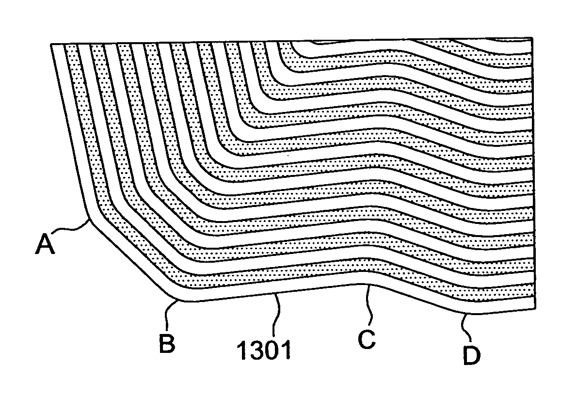
In accordance with one embodiment of the invention, a path planner and method for planning a path of a vehicle defines a reference row having a reference contour in a work area. A representation of the defined reference row is established. The defined reference row comprises a curved component, a generally linear component, or both. A generator generates one or more contour rows with a tracking contour that tracks or mirrors the reference contour based on a vehicular width and a radius difference parameter associated with the curved component. The contour rows are generated by a translation technique for the generally linear component and a radius modification technique for the curved component.

Description

[0001]This is a continuation-in-part of Ser. No. 10 / 403,681, filed Mar. 31, 2003 now U.S. Pat. No. 7,010,425, and entitled “A PATH PLANNER AND METHOD FOR PLANNING A PATH OF A WORK VEHICLE.”FIELD OF THE INVENTION [0002]This invention relates to a path planner and method for planning a contour path of a vehicle.BACKGROUND OF THE INVENTION [0003]A path planner may be used to determine one or more path plans for a vehicle to cover a work area. The work area may represent a field for growing a crop or other vegetation. The vehicle may need to traverse the entire work area or a portion thereof to plant a crop (or precursor thereto), treat a crop (or precursor thereto), or harvest a crop, for example. If the path plan is limited to linear rows, the execution of the path plan may consume more energy than desired to traverse sloped terrain or a work area of a particular shape. Accordingly, there is a need for a system and a method for applying contour path plan for the vehicle to the work ar...

Claims


Application Information

Patent Timeline
Patent Type & Authority Patents(United States)
IPC IPC(8): G08G1/123G06F19/00A01B69/04
CPCA01B79/005A01B69/008G05D1/0219
Inventor FLANN, NICHOLAS SIMONHANSEN, SHANE LYNNGRAY, SARAH ANN
Owner DEERE & CO
Learn More